Lighting / Emergency Lighting
User Guide for Spectrum SONU Modem
Quick guide for the Spectrum SONU 10G EPON Fiber Voice Modem. Learn about port connections, LED status indicators, device reset procedures, and safety requirements.
Table of contents
Manual images
Click an image to enlargeQuick guide from the manual
This document provides essential setup and operational information for the Spectrum SONU 10G EPON DPoE Advanced Fiber Voice Modem. It covers device connections, LED status indicators, and reset procedures. For connectivity issues, refer to spectrum.net/support or contact Customer Service at (800) 495-6590.
Safety Notices
To ensure safe operation, please observe the following:
- Power Requirements: The unit requires an input of 100-127Vac, 50-60Hz and uses a 12Vdc 1.5A power adapter. Ensure the AC plug is keyed for proper polarization and the DC barrel is fully inserted into the power port.
- Disconnecting: If the device is damaged or shows abnormalities, disconnect the power adapter from the wall outlet immediately.
- Environment: Install the device in a location with an operating temperature between 32°F (0°C) and 104°F (40°C). The maximum operating altitude is 3962 m (13000 ft).
Device Connections
The rear panel features the following ports:
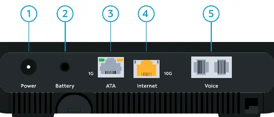
- 10G Ethernet (Internet): Connect to an Ethernet-enabled device such as a wireless access point, router, or LAN switch using an RJ45 cable.
- 1G Ethernet (ATA): Connect to an Ethernet-enabled ATA or IP Phone.
- Battery: Connect to the eBBU using the USC link cable provided by the eBBU vendor. This port is for signal data and alarms only.
- Power: Connect to the eBBU DC output cable or the supplied power adapter.
- Voice 1-2: Connect analog telephones or a DECT base station. Telephone service must be enabled via spectrum.net/support.
Device Reset
The reset button allows you to restart or factory reset the device:
- Restart: When the front panel lights are illuminated, press and hold the reset button for 4 seconds to initiate a power cycle.
- Factory Reset: Press and hold the reset button for 10 seconds to reset the device to factory default settings. Note that all settings will be deleted.
Front Panel LED Indicators
The status lights on the top of the device indicate operational states:

- Status Light: Indicates power-up (flashing blue), connection finding (pulsing blue), normal operation (solid blue), PON not operational (pulsing red), or loss of signal (pulsing red/white).
- Voice Light: Indicates service provisioning status and phone off-hook status.
- Firmware Upgrade: Indicated by a specific loop pattern of the Status, Voice, and Battery LEDs.
Back Panel LED Behavior
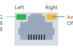
The Ethernet ports feature LED indicators to show speed and activity:
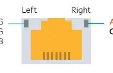
- 10G Internet Port: Left LED indicates speed (Green for 10G, Amber for 1G, Off for 100MB). Right LED indicates activity (Amber blinking).
- 1G ATA Port: Left LED indicates speed (Green for 1G/100MB, Off for 10MB). Right LED indicates activity (Amber blinking).
Official resources from the manual
Practical help
Common problems
Connectivity issues
Refer to the support article at spectrum.net/support or call Customer Service at (800) 495-6590.
Device damaged or abnormal behavior
Disconnect the power adapter from the AC wall outlet immediately.
Before use
- Ensure the power adapter AC plug is keyed for proper polarization.
- Ensure the DC barrel is fully inserted into the power connector port.
- Verify the installation location is within the temperature range of 32°F to 104°F (0°C to 40°C).
- Ensure the device is not installed above 3962 m (13000 ft) altitude.
- Ensure telephone service is enabled via spectrum.net/support before connecting phones.
Specs in practice
- Power Output
- 12Vdc 1.5A
- Operating Temperature
- 32°F to 104°F (0°C to 40°C)
- Max Altitude
- 3962 m (13000 ft)
Images and diagrams
- Port 1 (Power): Use only provided adapter or external backup battery (EBBU).
- Port 2 (Battery): Serial port for EBBU communications.
- Port 3 (1G): 1G Ethernet port for external ATA.
- Port 4 (10G): 10G Ethernet port for internet.
- Port 5 (Voice 1 & 2): 2 FXS lines of carrier-grade VoIP.
Model compatibility
- 1G ATA port is for external voice expansion only.
- Battery port is only for eBBU signal data and alarms.

Manual page author
David Miller
Documentation analyst
Organizes user manual content into clear summaries, with attention to model details, product context, and everyday usability.