Lighting / Fixtures
Installation Guide for Resistex Hyperline
Quick installation guide for the Resistex Hyperline linear lighting fixture. Includes mounting steps, wiring diagrams, and power configuration settings.
Table of contents
Manual images
Click an image to enlargeQuick guide from the manual
This document provides installation and configuration instructions for the Resistex Hyperline linear lighting fixture. Installation must be performed by a professional installer in compliance with electrical standards. Ensure the power is disconnected before starting any work.
Safety and Maintenance
Safety Notes:
- Never work on the luminaire while it is under voltage.
- The installation must be performed by a professional installer in compliance with electrical standards and regulations.
- Risk of electrostatic discharges (ESD). Handle with precautions.
- Follow all mounting steps described in this guide.
Maintenance Instructions:
- Do not use chemicals or abrasive products to clean the fixture.
- Keep these instructions for future dismantling or maintenance.
Installation
The installation process involves mounting the fixture to the ceiling or suspension system and connecting the electrical wiring. Follow the visual steps provided in the manual (Steps 1-16) to ensure correct assembly. Ensure the fixture is securely clicked into place during the mounting process.
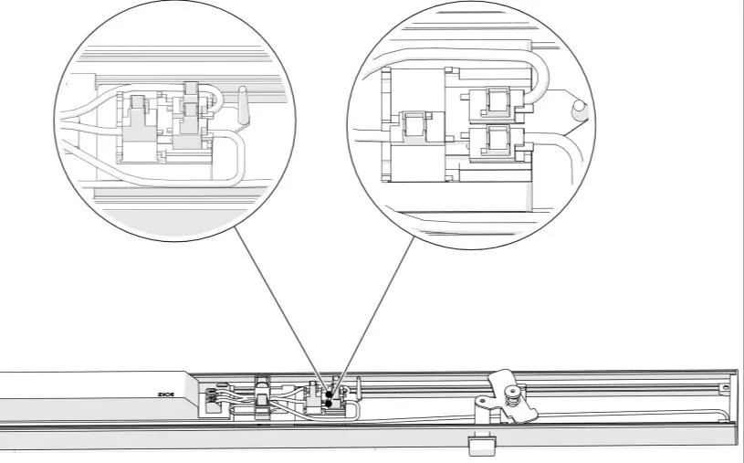
Wiring and Configuration
The fixture supports specific wiring configurations and power settings via DIP switches. Ensure the wiring (L1, N, L2, L3) is connected correctly according to the diagram. The power output can be adjusted using the DIP switches on the driver.
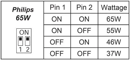
Power Settings (Philips 65W Driver):
- 65W: Pin 1 ON, Pin 2 ON
- 55W: Pin 1 ON, Pin 2 OFF
- 46W: Pin 1 OFF, Pin 2 ON
- 37W: Pin 1 OFF, Pin 2 OFF
Power Settings (BK-BEN060-A0350AS Driver):
- 32W: Switch 3 ON
- 40W: Switch 2 ON
- 50W: Switch 1 ON
- 60W: Switch 350mA setting
Practical help
Common problems
Electrostatic discharge risk
Handle components with precautions as per ESD norms.
Voltage presence
Never work on the luminaire while it is under voltage; ensure power is off.
Incorrect power output
Verify the DIP switch settings on the driver against the wattage configuration tables provided in the manual.
Before use
- Ensure a professional installer is performing the installation.
- Verify that the power supply is disconnected.
- Check that the mounting surface is suitable for the fixture weight.
- Confirm the wiring configuration (L1, N, L2, L3) matches the diagram.
- Ensure all parts are clicked securely into place during assembly.
Specs in practice
- Philips 65W Driver
- Adjustable wattage output via 2-pin DIP switch (37W to 65W).
- BK-BEN060-A0350AS Driver
- Adjustable wattage output via 3-pin DIP switch (32W to 60W).
Images and diagrams
- Steps 1-11: Initial assembly and wiring connection.
- Steps 12-16: Final mounting and securing of the fixture.
- Wiring Diagram: Shows connection points for L1, N, L2, L3.
- DIP Switch Tables: Guide for configuring wattage output.
Model compatibility
- Installation must comply with local electrical standards.
- Use only specified cable types (e.g., HO5RN-F, U-1000 R2V).

Manual page author
Michael Turner
Technical manual editor
Reviews PDF manuals for structure, safety notes, and practical product details so readers can find the right information quickly.