Electronics / Speakers Soundbars
Installation Guide for RetroSound 068216476M Kick Panels
A comprehensive installation guide for RetroSound 068216476M custom kick panels. Includes step-by-step instructions for wiring, speaker mounting, panel installation, and safety precautions.
Table of contents
Manual images
Jump to the sectionQuick Guide for Installation
This guide provides the necessary steps to install your RetroSound Kick Panels. Before beginning, ensure you have read all instructions carefully. Important: Always disconnect the negative (-) battery terminal before starting any work to prevent electrical damage, fire, or injury. Consult a professional installation specialist if you are unsure about any part of the process.
Installation Steps
- Remove Existing Kick Panels: Remove any screws or press clips holding the factory panels in place. You may need to remove the rubber door seal first.
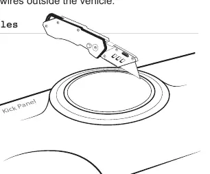
- Route Speaker Wires: Route wires before installing speakers. Avoid sharp edges that could fray wiring; use rubber grommets when passing wires through metal panels. Never run wires outside the vehicle.
- Cut Speaker Holes (Optional): If using larger speakers, use a speaker grill ring as a template to mark the required space and mounting screw locations. Use a razor knife or Dremel tool to enlarge the opening and a 1/8-inch drill bit for mounting holes.
- Mount Kick Panels: Secure the new panels using the fasteners from the factory kick panels. You may need to drill new mounting holes in the kick panels before installation.
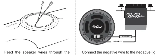
- Connect the Speakers: Feed wires through the speaker opening. Connect the negative wire to the negative (-) terminal and the positive wire to the positive (+) terminal.
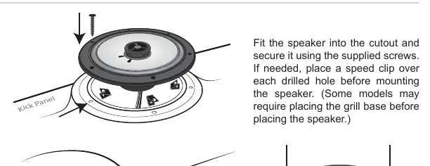
- Mount the Speakers: Fit the speaker into the cutout and secure it using the supplied screws. If needed, place a speed clip over each drilled hole before mounting. Some models may require placing the grill base before the speaker.
- Complete the Installation: Tighten all screws until the speaker is snug to prevent rattling, but be careful not to overtighten. Place the grill (if included) over the installed speaker.
Tips and Maintenance
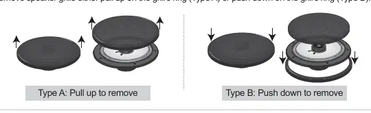
Removing Speaker Grills: Depending on the grill type, you can remove them by either pulling up on the grill's ring (Type A) or pushing down on the grill's ring (Type B).
Warranty Information
RetroSound Kick Panels come with a one-year manufacturer's warranty covering defects in materials and workmanship. Note that these panels are designed to be modified to fit your specific requirements; however, once modified, they are no longer covered by this warranty. Verify the speaker and vehicle fit before performing any modifications. For warranty issues, contact [email protected] or call 888.325.1555 to obtain a Return Authorization (RA) number.
Practical help
Common problems
Speaker rattling after installation
Ensure all screws are tightened until the speaker is snug, but avoid overtightening which can damage the panel or speaker.
Wire fraying or cutting
Always use rubber grommets when routing speaker wires through metal panels to protect the insulation.
Panel does not fit existing holes
You may need to drill new mounting holes in the kick panels before mounting them to the vehicle.
Before use
- Disconnect the negative (-) battery terminal.
- Check the installation area for gas tanks, fuel lines, brake lines, or electrical wiring before drilling.
- Verify speaker and vehicle fit before making any modifications.
- Use high-quality connectors to prevent signal loss and fire hazards.
- Ensure you have a razor knife or Dremel tool if enlarging speaker openings.
Specs in practice
- 1/8-inch drill bit
- Recommended size for drilling new mounting holes in the kick panels.
Images and diagrams
- Wiring diagram illustrates the correct connection of positive and negative wires to the speaker terminals.
- Grill removal diagrams show two methods (Type A and Type B) for removing speaker grills.
Model compatibility
- Panels are designed to be modified to fit specific requirements.
- Modification of the panels voids the manufacturer's warranty.

Manual page author
Emily Carter
User documentation editor
Prepares concise manual descriptions and highlights the most useful setup, operation, and maintenance information for readers.