Electronics / Audio
User Guide for RetroSound 068DALM1B Dallas M1B Receiver
Quick start guide for the RetroSound 068DALM1B Dallas M1B receiver. Learn how to install the radio face, connect wiring, and operate controls, presets, and system settings.
Table of contents
Manual images
Jump to the sectionQuick guide from the manual
This document provides essential instructions for installing and operating the RetroSound 068DALM1B Dallas M1B receiver. Key steps include connecting the ribbon cable, assembling the control shafts, mounting the brackets, and configuring basic radio settings. Always look for the orange bag containing the necessary screws before starting installation.
What's in the Box
Ensure your package contains the following components:
- Dallas Face
- Shafts and Knobs
- Brackets (J or K)
- Hardware (screws, nuts, washers, spacers)
- Wiring Adapters
Installation
Follow these steps to install the radio face:
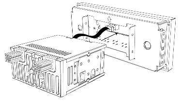
- Ribbon Cable: Plug the ribbon cable from the Radio Motor into the Radio Face.
- Control Shafts: Place a small metal spacer on each control shaft and secure with a shaft nut. Slide the shafts through the Radio Face with the shaft's cord facing out. Plug the control shafts into the Radio Motor.
- Shaft Finishing: Place the small black plastic washer and the thin metal washer onto the shaft. Secure with the shaft nut using a deep-well socket. Do not overtighten. Install the front and rear knobs.
- Brackets: With the radio facing you, attach the bracket labeled R to the right side and the bracket labeled L to the left side. Line up the tabs and use the supplied screws to secure the brackets to the Radio Face.
- Wiring: If your vehicle has a compatible factory harness, plug the optional wiring adapters into the factory harness and match the wiring color to the adapter from the Radio Motor. Cap off any unused wires.
- Final Assembly: Attach the Radio Face to the Radio Motor using the four small screws found in the orange bag.
Control Layout
The receiver features the following controls:
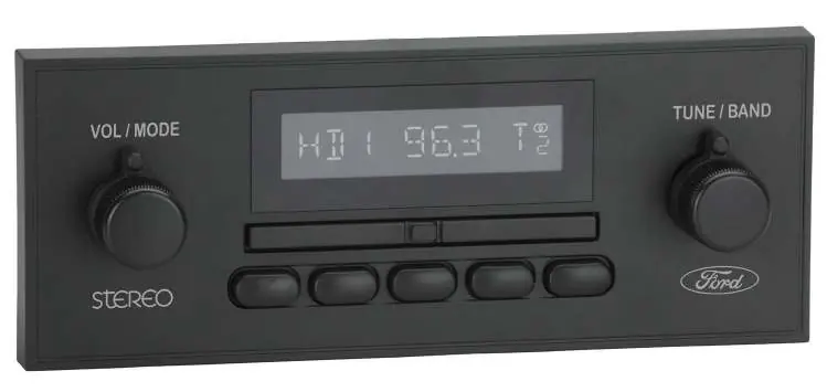
- Left-Front Knob (1): Power, Volume, EQ, Source.
- Left-Rear Knob (2): Source modes.
- Right-Front Knob (3): Tune, Mute, System Settings.
- Right-Rear Knob (4): Radio bands.
- Preset Buttons (5): Radio presets.
- Seek Bar (6): Previous/next station or track.
Basic Operation
Power On/Off: Press the Left-Front Knob (1) to power on. Press and hold to power off.
Volume: Rotate the Left-Front Knob (1).
Changing Source Modes: Rotate the Left-Rear Knob (2) clockwise.
Changing Radio Bands: Rotate the Right-Rear Knob (4) counter-clockwise.
Tune: Rotate the Right-Front Knob (3).
Equalizer (EQ): Press the Left-Front Knob (1) to enter the Tone Control sub-menu. Rotate to adjust settings.
System Settings: Press and hold the Right-Front Knob (3) to enter the sub-menu. Options include Clock (CLK), Display Color (SCAN), and Beep On/Off.
Radio Presets
Setting Presets: Tune to the desired station, then press and hold the desired Preset Button (5) for two seconds.
Recalling Presets: Simply press the Preset Button (5) corresponding to the saved station.
Practical help
Common problems
Radio does not turn on
Check the power connection and ensure the wiring is secure.
Shaft nut is loose or damaged
Use a deep-well socket to secure the nut, but do not overtighten.
Wiring does not match factory harness
Use the provided optional wiring adapters if compatible. Cap off any unused wires that do not match the factory harness.
Before use
- Locate the orange bag containing the necessary screws.
- Identify whether to use brackets J or K based on your installation.
- Ensure the ribbon cable is securely plugged into the Radio Motor.
- Verify if your vehicle has a compatible factory harness for the wiring adapters.
Specs in practice
- Left-Front Knob (1)
- Primary control for Power, Volume, EQ, and Source selection.
- Right-Front Knob (3)
- Primary control for Tuning, Muting, and accessing System Settings.
- Left-Rear Knob (2)
- Used for cycling through source modes.
- Right-Rear Knob (4)
- Used for cycling through radio bands.
Images and diagrams
- The assembly diagram shows the correct order of spacers, washers, and nuts on the control shafts.
- The bracket installation diagram illustrates attaching the L and R brackets to the Radio Face.
Model compatibility
- Optional wiring adapters are for vehicles with compatible factory harnesses.
- Some features, such as Display Color, are not available on all radio models.

Manual page author
Michael Turner
Technical manual editor
Reviews PDF manuals for structure, safety notes, and practical product details so readers can find the right information quickly.