Electronics / Speakers Soundbars
RetroSound Stereo Speakers Installation Guide
Installation guide for RetroSound stereo speakers. Includes wiring instructions, mounting steps, grill removal tips, and technical specifications for various models.
Table of contents
Manual images
Jump to the sectionQuick Guide
This guide provides essential installation steps for RetroSound stereo speakers. Before beginning, it is highly recommended to consult a professional installation specialist. Always disconnect the negative (-) battery terminal before starting any work to prevent damage, fire, or injury. Ensure you check the installation area for hidden obstacles like fuel lines, brake lines, or electrical wiring before drilling.
Installation Preparation
Ensure you have all necessary components included in the box: two speakers, two speaker grills (on select models), two sets of speaker wire, and mounting hardware. You will also need the following tools:
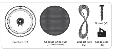
- Phillips screwdriver
- Handheld drill
- 1/8-inch drill bit
- Wire strippers, crimpers, or cutters
Determine the mounting location by ensuring the area is large enough for the speaker diameter and has sufficient mounting depth. If installing in a vehicle door, verify that the speaker does not obstruct windows, door locks, or other moving parts.
Wiring and Connection
Route the speaker wires before installing the speakers. Avoid running wires outside the vehicle and keep them away from sharp edges; use rubber grommets if routing through metal panels. To connect the speakers:
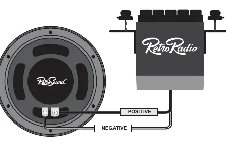
- Feed the speaker wires through the speaker opening.
- Connect the negative wire to the negative (-) speaker terminal.
- Connect the positive wire to the positive (+) speaker terminal.
- Use high-quality connectors to minimize signal loss.
Mounting the Speakers
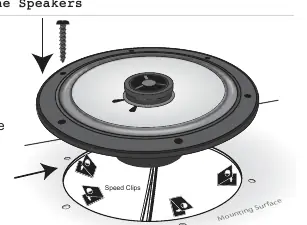
- Fit the speaker into the cutout.
- If necessary, place a speed clip over each drilled hole before mounting.
- Secure the speaker using the supplied screws.
- Tighten all screws until the speaker is snug to prevent rattling, but be careful not to overtighten.
- Place the grill (if included) over the installed speaker.
Grill Removal
To remove the speaker grills, follow the method corresponding to your model:
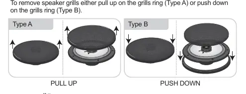
- Type A: Pull up on the grill ring.
- Type B: Push down on the grill ring.
Specifications
The manual includes a detailed specification chart for various RetroSound models (S-42, S-52, S-412, S-62, R-352N, R-452N, R-463N, R-483N, R-525N, R-652N, R-693N). Key parameters listed include nominal diameter, impedance, frequency response, sensitivity, power handling (RMS/peak), and mounting depth.
Warranty
The unit comes with a one-year manufacturer's warranty covering defects in materials and workmanship. To handle a warranty issue, contact [email protected] or call 888.325.1555 to obtain a Return Authorization (RA) number. Returns without an RA number will be refused.
Practical help
Common problems
Speaker obstruction in doors
Check all door functions (windows, locks) through their entire range of motion before finalizing the mounting location.
Wiring damage
Avoid running wires over sharp edges; use rubber grommets when routing through metal panels.
Signal loss
Always use high-quality connectors for the best quality connection.
Rattling after installation
Tighten all screws until the speaker is snug, but do not overtighten.
Before use
- Disconnect the negative (-) battery terminal.
- Check the installation area for gas tanks, fuel lines, brake lines, or electrical wiring before drilling.
- Verify mounting depth and diameter against the specification chart.
- Gather necessary tools: Phillips screwdriver, drill, 1/8-inch bit, wire strippers/crimpers.
Specs in practice
- Nominal Impedance
- Standard electrical resistance of the speaker, typically 4 ohm for these models.
- Power Handling
- The RMS/Peak wattage the speaker can handle; ensure your radio output matches these ratings.
- Mounting Depth
- The required clearance behind the mounting surface to accommodate the speaker magnet.
Images and diagrams
- Wiring diagram illustrates connecting the speaker terminals to the radio unit.
- Mounting diagram shows the correct placement of speed clips and screws into the mounting surface.
- Grill removal diagram distinguishes between Type A (pull up) and Type B (push down) mechanisms.
Model compatibility
- Speaker grills are included on select models only.
- Refer to the specification chart on page 5 for specific model dimensions and requirements.

Manual page author
Michael Turner
Technical manual editor
Reviews PDF manuals for structure, safety notes, and practical product details so readers can find the right information quickly.