Power / Batteries & Chargers
User Manual for Rich Solar RS-DC Series DC-DC Battery Charger
Quick guide for the Rich Solar RS-DC Series battery charger. Learn about installation, wiring, D+ ignition setup, battery type selection, and troubleshooting for models RS-DC20, RS-DC40, and RS-DC60.
Table of contents
Manual images
Click an image to enlargeQuick Guide
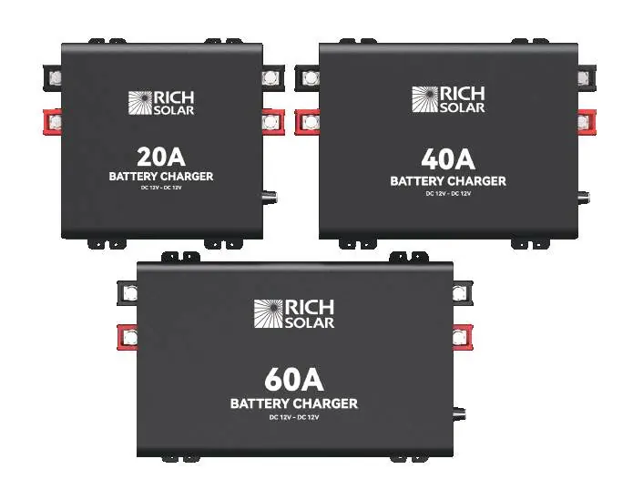
The Rich Solar RS-DC Series battery chargers are designed to charge auxiliary or house batteries from an alternator or starter battery. They feature a 3-stage charging process and are compatible with AGM, Flooded, GEL, Sealed, Lithium-iron Phosphate, and Lithium-ion 12V batteries. The unit includes built-in protections against over-voltage, over-temperature, and reverse polarity.
Safety Instructions
Warning: Risk of electric shock, fire, or injury. Follow these safety guidelines:
- Use only with 12V battery banks.
- Ensure positive and negative terminals do not touch.
- Install in a dry, cool, and well-ventilated area.
- Do not operate in environments with explosion risks, corrosive fumes, or high dust levels.
- Disconnect the product from the battery before cleaning or making circuit changes.
- Do not attempt to repair the charger yourself.
Installation
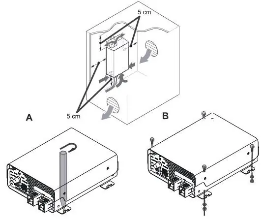
For optimal performance, ensure the charger is mounted as close as possible to the auxiliary battery. Maintain at least 5cm (1.97 inches) of clearance on all sides for ventilation. Secure the unit to a surface using 4 screws.
Wiring and Fusing
The installer is responsible for using correct cable and fuse sizes. Prioritize shorter, thicker wires to minimize voltage drop. The system requires a common negative ground point.
D+ Ignition Wiring
The charger will not operate until the D+ ignition cable is connected to a 12V ignition source. This ensures the charger only runs when the vehicle's engine is running, preventing the starter battery from draining. Use 18-16AWG solid copper cable for this connection.
LC Current Limit Wiring
Connecting the LC terminal to a 12V power supply limits the charger to 50% of its rated current. This is optional and can be connected to the same ignition source as the D+ wire.
Operation
The charger features a mode selection switch to set the battery type (STD, GEL, AGM, LFP). Ensure the switch is set to the correct battery type before operation. The unit includes an LED indicator to signal faults.
Troubleshooting
If the charger is not functioning, check the LED status:
- Red Fault LED ON: Indicates a fault such as Battery Overvoltage, Battery Undervoltage, Polarity Reverse, or High Temperature. Refer to the troubleshooting section to measure voltages and check wiring.
- ALL Indicator LED OFF: Often caused by an incorrect D+ connection or a connection break. Verify the D+ signal and check all wiring and fuses.
Maintenance
Periodically inspect wiring for cracks, wear, or corrosion. Ensure all terminals remain tight, as vehicle vibrations can loosen connections. Keep the unit free of dust and ensure ventilation remains unobstructed.

Technical Specifications
The RS-DC series is available in 20A, 40A, and 60A models. All models operate on a 12VDC nominal input voltage with an operating range of 10-16VDC. Efficiency is rated at >85% at 14VDC with a 30% load.
Practical help
Common problems
Red Fault LED ON: Battery Overvoltage (15.5-16V)
Disconnect other chargers in the circuit and let the battery rest to lower the voltage.
Red Fault LED ON: Battery Undervoltage (below 8-10V)
Disconnect other loads and let the battery charge. Lead acid batteries below 8V may require an external charger.
Red Fault LED ON: Polarity Reverse
Use a multi-meter to verify positive and negative connections. Fix wiring if the reading is negative.
ALL Indicator LED OFF
Verify D+ ignition cable is connected to a live 12V source. Check fuses and wiring continuity.
Before use
- Verify the battery bank is 12V.
- Ensure proper cable sizing based on the model and cable length.
- Identify a 12V ignition source for the D+ terminal.
- Ensure the installation area is dry, cool, and well-ventilated.
- Check that all connections are tight and secure.
Specs in practice
- Output nominal power
- Maximum power output (250W for 20A, 500W for 40A, 750W for 60A).
- Operating voltage range
- The input voltage range (10-16VDC) within which the charger operates.
- Float charging current
- Low maintenance current applied after absorption to prevent battery discharge.
Images and diagrams
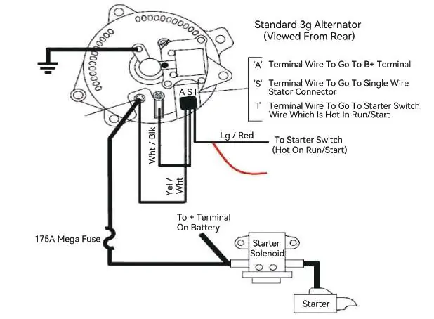
- Wiring diagram illustrates connections for the Alternator, Starter Battery, and House Battery.
- Installation diagram shows the required 5cm clearance for proper ventilation.
Model compatibility
- Compatible with AGM, Flooded, GEL, Sealed, Lithium-iron Phosphate, and Lithium-ion 12V batteries.
- Not for use with 24V batteries.
- Temperature sensor is not to be used with Lithium batteries.

Manual page author
Michael Turner
Technical manual editor
Reviews PDF manuals for structure, safety notes, and practical product details so readers can find the right information quickly.