Power / Batteries & Chargers
User Manual for Rich Solar 2000W Pure Sine Wave Inverter
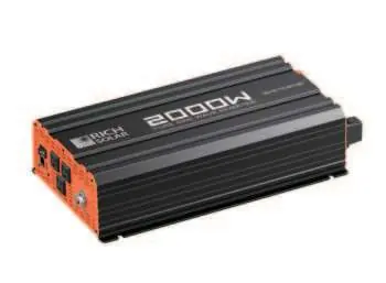
Comprehensive user guide for the Rich Solar 2000W Pure Sine Wave Inverter (RS-V2P12/RS-V2P24). Includes installation instructions, safety warnings, battery bank setup, troubleshooting, and technical specifications.
Quick answers from the manual
Quick answer
- The Rich Solar 2000W Pure Sine Wave Inverter converts 12V or 24V DC battery power into 120V AC power. It includes safety features like overload, short circuit, and over-temperature protection. p. 3, 4
Key actions
- Mount the inverter in a secure, well-ventilated location. p. 11
- Connect the DC input cables (Positive/Negative) and the ground wire. p. 11
First start
- Ensure the power switch is OFF, connect the battery cables, turn the switch to ON, and verify the green Power LED is lit. p. 11, 12
Problems and fixes
Fault LED is lit
Turn off appliances, allow to cool, check for overload or low voltage.
p. 6, 13Maintenance and reset
- If the inverter shuts down, turn it off, resolve the fault (overload/heat/voltage), and restart. p. 6, 13
Technical specifications
| Parameter | Value | Meaning | Pages |
|---|---|---|---|
| Output Power | 2000W | Continuous power output | p. 4 |
| Peak Surge | 4000W | Maximum surge power | p. 4 |
| Input Voltage | 12V DC/24V DC | Supported DC input | p. 4 |
| Output Voltage | 120V AC | AC output voltage | p. 4 |
Where to find it in the PDF
- Front Panel p. 6
- Rear Panel p. 8
- Specifications p. 4
Table of contents
Manual images
Click an image to enlargeImportant Information from the Manual
This manual provides essential safety and operating instructions for the Rich Solar 2000W Pure Sine Wave Inverter. It is designed to convert 12V or 24V DC power into 120V AC power for household appliances. Before installation, ensure you have the correct model (RS-V2P12 or RS-V2P24) and that your battery bank is properly configured for the load requirements.
Safety Warnings
- Lethal Output: The inverter output is equivalent to a household AC outlet. Treat it with the same caution.
- Ventilation: Keep the inverter in a dry, well-ventilated area. Do not block cooling vents.
- Explosion Hazard: Do not operate near flammable fumes, gases, or in enclosures with unsealed lead-acid batteries.
- Polarity: Incorrect battery polarity will damage the inverter and void the warranty.
- No User Serviceable Parts: Do not open the inverter casing.
Front Panel Overview
The front panel includes the following features:
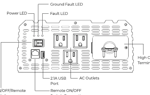
- ON/OFF Switch: Controls AC output.
- Power LED (Green): Indicates normal operation.
- Ground Fault LED (Yellow): Indicates an interrupted ground fault circuit.
- Fault LED (Red): Indicates shutdown due to overheating, overload, under voltage, or over voltage.
- AC Outlets: Three outlets for connecting appliances.
- USB Power Port: 5V/2.1A output for charging small electronics.
- Remote ON/OFF Switch Connection: Port for an optional wired remote.
Rear Panel and Connections
The rear panel contains:
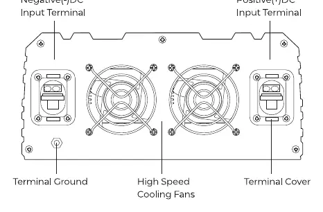
- DC Input Terminals: Positive (+) (Red) and Negative (-) (Black) terminals for battery connection.
- Cooling Fans: Thermally controlled high-speed fans.
- Terminal Ground: For connecting an insulated 10-gauge safety ground wire to the vehicle chassis or earth ground.
Installation and Battery Bank Setup
Proper planning is required for a safe installation:
- Battery Bank: Use deep-cycle, sealed lead-acid batteries.
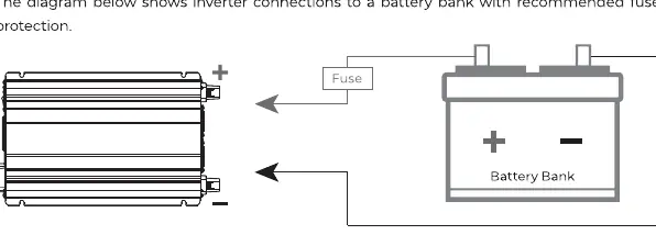
- Fusing: Install a fuse on the positive (+) battery cable as close to the battery terminal as possible.
- Wiring: Use the proper gauge wire for your installation. Ensure all connections are tight and secure.
- Grounding: Connect the ground terminal to a proper grounding point (vehicle chassis or earth ground) using a 10-gauge copper wire.
- Mounting: Mount the inverter in a secure location, preferably horizontally, ensuring free airflow around the unit.
Troubleshooting
If the inverter shuts down or displays a fault:
- Fault LED Lit: Check for overload, overheating, or low/high battery voltage.
- Buzzing Sound: Often indicates low battery voltage or poor cable connections.
- No Output: Check battery terminals, fuse, and the ON/OFF switch position.
Practical help
Common problems
Fault LED is lit (Red)
Turn off all AC appliances, allow the inverter to cool, and check for overload, under voltage, or over voltage conditions.
Continuous buzzing sound
Check for low battery voltage, poor/loose cable connections, or excessive voltage drop. Recharge or replace the battery.
Inverter shuts down automatically
Ensure the load does not exceed the rated capacity, check for adequate ventilation, and verify battery voltage is within the operating range.
Before use
- Verify the input voltage (12V or 24V) matches your battery bank.
- Ensure the battery bank consists of deep-cycle, sealed lead-acid batteries.
- Install a fuse on the positive cable as close to the battery as possible.
- Connect a 10-gauge copper wire from the ground terminal to a proper grounding point.
- Ensure the ON/OFF switch is in the OFF position before making connections.
- Check that ventilation vents are clear of obstructions.
Specs in practice
- Output Power
- 2000W continuous power capacity.
- USB Power Port
- 5V/2.1A output for charging tablets, e-readers, and smartphones.
Images and diagrams
- Front Panel: Identifies the location of the Power switch, LED indicators, AC outlets, and USB port.
- Rear Panel: Shows the location of DC input terminals, cooling fans, and the ground terminal.
- Battery Connection: Illustrates the correct placement of the fuse on the positive cable between the battery and the inverter.
Model compatibility
- Compatible with 12V or 24V DC power sources depending on the specific model.
- Not for use with appliances requiring neutral-to-ground bonded AC input.
- Do not connect to utility power AC distribution wiring.

Manual page author
Michael Turner
Technical manual editor
Reviews PDF manuals for structure, safety notes, and practical product details so readers can find the right information quickly.