Electronics / Speakers & Soundbars
Repair Guide for Samsung HW-B400F/ZC Soundbar
Professional repair guide for the Samsung HW-B400F/ZC soundbar. This document provides essential safety precautions, ESD handling instructions, and detailed step-by-step procedures for the disassembly and assembly of internal components...
Quick answers from the manual
Quick answer
- This document is a professional repair guide for the Samsung HW-B400F/ZC soundbar, providing instructions for safe disassembly, component replacement, and reassembly. p. 1, 4
Key actions
- Remove the bottom cover by unscrewing 14 screws. p. 10
- Disconnect the Main PCB and SMPS by removing 5 screws and 3 cables. p. 11
Where to find it in the PDF
- Safety Precautions p. 5, 6, 7, 8
- Disassembly and Assembly p. 10, 11, 12, 13
Table of contents
Manual images
Click an image to enlargeImportant Safety Information
This document is intended for professional repair and service. Before performing any maintenance, observe the following safety protocols to prevent electrical shock, fire, or damage to the unit:
- Disconnect Power: Always unplug the AC power cord from the power source before attempting to remove or reinstall any component.
- ESD Protection: The device contains Electrostatically Sensitive Devices (ESDs). Drain electrostatic charge from your body before handling components, use a grounded-tip soldering iron, and do not remove replacement parts from protective packaging until ready for installation.
- Safety Checks: Perform a Leakage Current Hot Check and Insulation Resistance Cold Check after reassembly to ensure the unit is safe for operation.
- Design Integrity: Do not alter the mechanical or electrical design of the unit. Use only original replacement parts with identical safety ratings.
Disassembly Procedures
Follow these steps in order to access internal components. Use only the provided jig or non-metal tools to pry apart the cabinet to avoid damage.
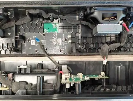
Separate Bottom Cover
Remove the 14 screws securing the bottom cover. Carefully pull out the cover and detach the two internal cables connecting to the P-Body.
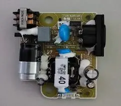
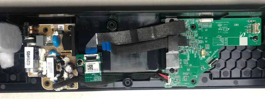
Separate Main PCB and SMPS
After removing the bottom cover, remove the 5 screws and 3 cables connecting the Main PCB and SMPS. Ensure all FFC cables (Key PCB, BT Module) are disconnected carefully.
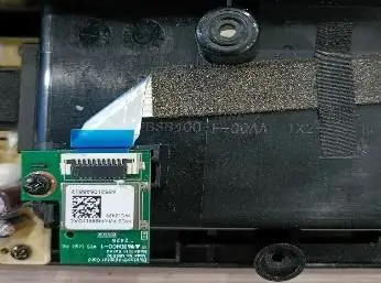
Separate BT Module
Detach the FFC cable and remove the single screw securing the Bluetooth module.
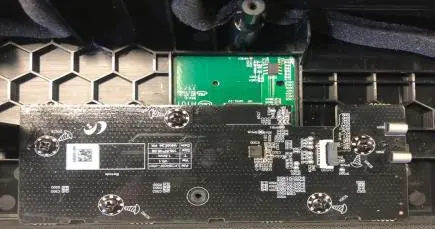
Separate KEY_LED PCB and NFC PCB
Remove the 5 screws securing the KEY_LED PCB. Separate it in a direction perpendicular to the plane. Note that the 6-pin connector between the KEY_LED and NFC PCB is fragile and requires careful handling. The NFC PCB is bonded with double-sided tape and may require a flat-head screwdriver for removal.
Assembly Procedures
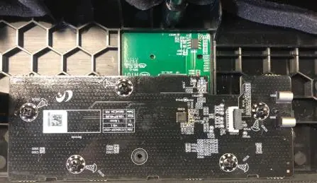
Assembly is performed in the reverse order of disassembly. Ensure all connectors are fully locked; an unlocked connector may cause the unit to malfunction. When installing the NFC PCB, ensure the surface is clean of residual tape before applying the new part.
Manufacturer information
Samsung Electronics
Practical help
Common problems
Connector malfunction
Check the locking status of all connectors. If a connector is unlocked, the unit may not function correctly.
NFC PCB adhesion failure
Ensure the top cover surface is clean of residual double-sided tape before installing the new NFC PCB.
ESD damage to components
Minimize body motion, use a grounded wrist strap, and touch a known earth ground before handling semiconductor components.
Before use
- Disconnect the AC power cord before servicing.
- Discharge residual voltage from the PCBA before handling.
- Ensure the work area is free of static electricity.
- Use only non-metal tools to pry apart the cabinet.
- Verify that all protective devices and compartment covers are restored after reassembly.
Show more Show less
Images and diagrams
- AC Leakage Test: Shows the connection between the device under test, leakage current tester, and earth ground.
- Insulation Resistance Test: Illustrates the measurement points between the shorted AC plug and exposed metal parts.
- PCB Layouts: Visual guides for screw locations and cable routing for the Main PCB, SMPS, and BT module.

Manual page author
Emily Carter
User documentation editor