Lighting / Motion Sensors
Instruction Manual for Saxby Icarus PIR 1LT Wall 81010
Quick guide for the Saxby Icarus PIR 1LT Wall (81010). Learn how to install, adjust the PIR sensor, use the manual override, and maintain your outdoor light.
Quick answers from the manual
Quick answer
- The Saxby Icarus PIR 1LT Wall (81010) is an outdoor light with an adjustable PIR sensor. It requires installation by a qualified electrician and uses a max 5W LED GU10 bulb. p. 1, 2
Key actions
- Install the unit vertically 1.8-2.5m above ground, ensuring the drain hole is at the bottom. p. 1, 2
- Adjust PIR settings (TIME, SENS, LUX) by flipping down the black cover. p. 1
- Toggle between Auto and Manual modes by switching power OFF and ON twice within 3 seconds. p. 1
First start
- After switching on, the PIR sensor requires a 1-minute 'warm-up' period before entering Auto mode. p. 1
Problems and fixes
Light stays on permanently
Switch power OFF and ON twice within 3 seconds to return to Auto mode.
p. 1Maintenance and reset
- Clean with a soft dry cloth; do not use solvents or abrasive cleaners. p. 1
Technical specifications
| Parameter | Value | Meaning | Pages |
|---|---|---|---|
| Voltage | 240V, 50Hz | Supply voltage | p. 1 |
| Bulb Type | Max 5W LED GU10 | Maximum bulb wattage and type | p. 1 |
| IP Rating | IP44 | Ingress protection rating | p. 1 |
Where to find it in the PDF
- Product Overview and PIR Adjustment p. 1
- Installation and Wiring p. 2
Table of contents
Manual images
Click an image to enlargeQuick guide from the manual
The Saxby Icarus PIR 1LT Wall (81010) is an outdoor light fitting equipped with a PIR sensor. It requires installation by a qualified electrician. The unit features an adjustable PIR sensor for detection distance, duration, and light sensitivity, as well as a manual override function.
Installation
Before starting, ensure the power is switched off at the mains. The unit must be installed in a vertical position, 1.8-2.5m above the ground. Ensure the mounting surface is solid, such as a brick or block wall.
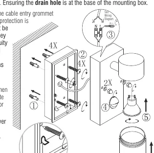
- Determine the position of the fitting, ensuring the ARROW on the base indicates the correct orientation.
- Fit the 2 threaded posts in the back plate.
- Use the back plate as a template to mark the 2 fixing holes.
- Secure the back plate to the wall, ensuring the drain hole is at the base.
- Connect the house wiring to the internal terminal block.
- Fit the terminal block onto the post in the back plate.
- Fit the front frame over the 2 threaded bolts and secure with the 2 threaded nuts.
- Fit the bulb and place the bulb covers.
Wiring
This is a Class II fitting and does not require an Earth connection. If earth cables are present, connect them to each other to maintain continuity throughout the property and insulate them. Connect the incoming mains to the terminal block as follows:
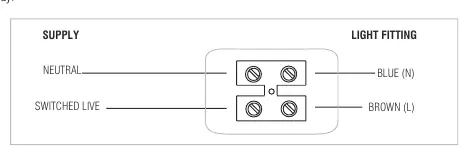
- Neutral: Blue (N)
- Switched Live: Brown (L)
PIR Sensor Adjustment
To access the adjustment screws, flip down the black cover over the PIR sensor. Use a small screwdriver to adjust the settings:
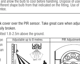
- TIME: Adjusts how long the lamp stays on (5 seconds - 5 minutes).
- SENS: Adjusts the detection distance (up to 8 metres).
- LUX: Adjusts the light level (10-2000 lux).
Manual Override
The PIR sensor has a manual override function:
- To enter Manual Mode: In Auto mode, switch the power OFF and ON twice within 3 seconds. The light will remain ON permanently.
- To return to Auto Mode: Switch the power OFF and ON twice within 3 seconds.
- Note: If the power is switched OFF for more than 6 seconds, the sensor will go through a 1-minute 'warm-up' process when turned on again.
Maintenance
Always switch off the power supply before changing lightbulbs or cleaning. Clean with a soft dry cloth; do not use solvents or abrasive cleaners. Ensure the bulb wattage does not exceed the maximum specified (5W LED GU10).
Technical Data
- Voltage: 240V, 50Hz
- Bulb Type: Max 5W LED GU10
- IP Rating: IP44
- IK Rating: IK05
- Class: Class II (Double Insulated)
Practical help
Common problems
Light stays on permanently
The unit is likely in Manual Mode. Switch the power OFF and ON twice within 3 seconds to return to Auto mode.
PIR sensor not detecting
Ensure the unit is installed 1.8-2.5m above the ground. Check if the sensor is obstructed or if the sensitivity (SENS) needs adjustment.
Light does not turn on
Check the bulb connection, ensure the power is on, and allow 1 minute for the PIR sensor to 'warm up' after switching on.
Before use
- Ensure power is switched off at the mains
- Verify mounting surface is solid (brick/block)
- Check that the drain hole is at the base of the mounting box
- Confirm bulb is max 5W LED GU10
- Ensure cable entry points are sealed to maintain IP rating
Specs in practice
- Manual Override
- Allows the light to stay ON permanently, bypassing the PIR sensor.
Images and diagrams
- Wiring diagram shows connection of Neutral and Switched Live to the terminal block.
- PIR adjustment screws (TIME, SENS, LUX) are located under the black cover.
- Installation diagram shows the sequence of mounting the back plate, connecting wires, and securing the front frame.
Model compatibility
- Requires H05RN-F specification cable (outdoor grade).
- Not suitable for earthing (Class II).
- Minimum distance to illuminated surface: 0.5m.

Manual page author
Emily Carter
User documentation editor
Prepares concise manual descriptions and highlights the most useful setup, operation, and maintenance information for readers.