Lighting / Fixtures
Instruction Manual for Saxby Toko Wall Light 61638/61639
Quick guide for the Saxby Toko Wall Light (61638, 61639). Includes installation steps, wiring diagrams, technical specifications, and safety warnings.
Quick answers from the manual
Quick answer
- The Saxby Toko Wall Light (61638/61639) is a non-dimmable, double-insulated wall light. It requires installation by a qualified electrician and must be connected to a circuit with a 30mA RCD. p. 1, 2
Key actions
- Install the wall light p. 2
- Wire the light p. 2
First start
- Switch on the power p. 2
Problems and fixes
Light not working
Check fuse/circuit breaker and ensure connections are tight.
p. 2Maintenance and reset
- Cleaning p. 1
Technical specifications
| Parameter | Value | Meaning | Pages |
|---|---|---|---|
| Voltage | 220-240 V~, 50 Hz | Operating voltage | p. 1 |
| Bulb Type | 3W LED Hi Power, 3000K | Light source specifications | p. 1 |
Where to find it in the PDF
- Technical Data and Safety p. 1
- Installation and Wiring p. 2
Table of contents
Manual images
Click an image to enlargeQuick guide from the manual
The Saxby Toko Wall Light (61638, 61639) is a fixed lighting fixture designed for indoor wall mounting. This product is double insulated and does not require an Earth connection. It is not suitable for dimming. Installation must be performed by a competent and qualified electrician in accordance with IEE Wiring Regulations.
Technical data
- Voltage: 220-240 V~, 50 Hz
- Bulb Type: 3W LED Hi Power, 3000K
- Insulation: Double Insulated (Class II)
- Energy Efficiency: Class G
Safety warnings
- Always switch off the power supply at the mains before installing or maintaining this fitting.
- Ensure other persons cannot restore the electrical supply without your knowledge.
- This light fitting should be connected to a fused circuit with a 30mA RCD fitted.
- The product contains non-replaceable parts and cannot be serviced; if damage occurs, the part should be scrapped.
- Replaceable control gear and LED light source must be handled by a professional.
Installation
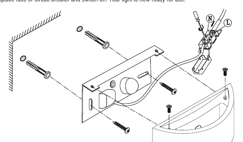
- Undo the screws at the top of the product to separate the shade from the fixing bracket.
- Using the fixing bracket as a template, mark the fixing holes, ensuring the wall bracket is horizontal.
- Use the supplied plugs (masonry only) and screws to secure the fixing bracket to the wall.
- Pull the mains cable through the hole.
- Wire the product as detailed in the wiring diagram.
- Refit the product to the fixing bracket and secure it by refitting the top fixing screws. Be careful not to trap any wiring.
- Replace the fuse or circuit breaker and switch on.
Wiring
Having identified the wiring from your existing light fitting, connect the wires to the approved outdoor-rated external terminal block as follows:
- Supply Neutral: Connect to Blue (N)
- Supply Switched Live: Connect to Brown (L)
Ensure that you have correctly identified the wires, connections are tight, and no loose strands have been left out of the connection block. Reseal the terminal block after connection.
Care and maintenance
We recommend cleaning with a soft dry cloth. Do not use solvents or abrasive cleaners as these could damage the finish. Always switch off the power supply before cleaning.
Practical help
Common problems
Light does not turn on
Check the fuse or circuit breaker. Ensure all wiring connections are tight and correctly identified.
Cannot dim the light
This product is not suitable for dimming.
Before use
- Ensure power is switched off at the mains.
- Verify you have all parts listed in the pack.
- Ensure the wall surface is suitable for the provided fixings.
- Confirm a 30mA RCD is fitted to the circuit.
- Ensure the mains supply cable has a minimum cross-sectional area of 1.0mm2.
Specs in practice
- Double Insulated
- The product does not require connection to an Earth circuit.
Images and diagrams
- The wiring diagram illustrates the connection of the Supply Neutral to the Blue (N) terminal and the Switched Live to the Brown (L) terminal.
Model compatibility
- Not suitable for dimming.
- Requires installation by a qualified electrician.
- Supplied plugs are for masonry only; use appropriate fixings for other surfaces.

Manual page author
Emily Carter
User documentation editor
Prepares concise manual descriptions and highlights the most useful setup, operation, and maintenance information for readers.