Power / Wireless Chargers
Installation Guide for Scanstrut ROKK Wireless Charge Hidden 10W
A comprehensive installation guide for the Scanstrut ROKK Wireless Charge Hidden 10W (SC-CW-01F). Includes detailed steps for surface preparation, mounting, wiring, and technical specifications for this 12/24V wireless charger.
Table of contents
Manual images
Click an image to enlargeQuick guide from the manual
The Scanstrut ROKK Wireless Charge Hidden 10W is designed for installation beneath a surface. For optimal charging performance, the mounting surface thickness should be 3mm. If the surface is thicker, routing is required. The unit is compatible with 12V and 24V systems and requires a waterproof wiring connection.
Parts List
- Locking Ring
- Magnet Installation Tool (with 2 magnets)
- 3x No6 x 1/2” Self-tapping screws
- Charger
- Self-adhesive EPDM Rubber
- Alcohol wipe
Tools Required
- Pozi Screwdriver
- Straight Router
- Sikaflex 292-i (Optional)
Technical Specifications
- Input voltage range: 10-30V DC (12/24V system)
- Input current max: 2A
- Output power: 10W (9V, 1.1A)
- Standby power draw: < 0.2W
- Waterproof rating: IPX6 (front and back)
Installation Instructions
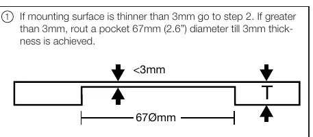
- Surface Preparation: If the mounting surface is thinner than 3mm, proceed to step 2. If it is greater than 3mm, use a router to create a 67mm diameter pocket until the surface thickness is 3mm.
- Locking Ring Installation: Screw or bond the locking ring to the underside of the surface. Orient the ring according to the measured material thickness (3-9mm, 3-18mm, or >18mm). Sikaflex 292-i is recommended for bonding.
- Top Surface Finish:
- Option 1: CNC etch the logo onto the top surface (do not exceed 0.5mm depth).
- Option 2: Use the provided adhesive EPDM rubber. Use the alcohol wipe to clean the surface first, then align using the provided magnet tool.
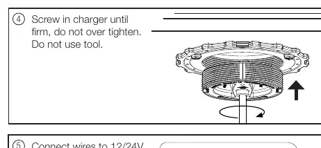
- Charger Installation: Screw the charger into the locking ring until firm. Do not over-tighten and do not use tools.
- Wiring: Connect the wires to a 12/24V supply. Ensure the connection is waterproof and install a fuse appropriate for the input voltage and current.
Practical help
Common problems
Surface too thick
If the mounting surface is thicker than 3mm, you must rout a 67mm diameter pocket until the remaining thickness is 3mm.
Over-tightening
Do not use tools to screw in the charger; tighten by hand until firm to avoid damage.
Before use
- Verify mounting surface thickness (must be 3mm for optimal performance).
- Ensure you have a 12/24V power supply.
- Prepare a waterproof connection for wiring.
- Ensure you have a fuse appropriate for the input voltage and current.
Specs in practice
- Input voltage
- 10-30V DC (compatible with 12V and 24V systems).
- Output power
- 10W (9V, 1.1A).
- Waterproof rating
- IPX6 (front and back).
Images and diagrams
- Step 2 shows how to orient the locking ring based on material thickness (3-9mm, 3-18mm, or >18mm).
- Step 5 illustrates the wiring connection to the 12/24V supply.
Model compatibility
- Compatible with 12V and 24V systems.
- Requires 3mm surface thickness for optimal charging.

Manual page author
Michael Turner
Technical manual editor
Reviews PDF manuals for structure, safety notes, and practical product details so readers can find the right information quickly.