Furniture / Home Furnishing
Operating and Mounting Instructions for Schmersal AZM 161CC-12/12KA-024 Solenoid Interlock
A comprehensive guide for the Schmersal AZM 161CC-12/12KA-024 solenoid interlock. This manual covers installation, electrical wiring, technical specifications, safety maintenance, and troubleshooting procedures.
Table of contents
Manual images
Click an image to enlargeQuick guide from the manual
This document provides essential information for the mounting, set-up, and commissioning of the Schmersal AZM 161CC-12/12KA-024 solenoid interlock. It is intended for authorized qualified personnel only. The device is classified as a type 2 interlocking device according to EN ISO 14119 and is designed to prevent safety guards from being opened before hazardous conditions are eliminated.
Product description
The AZM 161 series is a solenoid interlock available in various configurations. The ordering code defines specific features such as connection type (screw or cage clamps), contact configuration, latching force (5 N or 30 N), and release mechanisms (manual or emergency). The device is not intended for private consumers.
Mounting
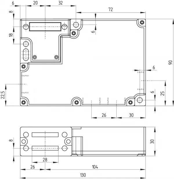
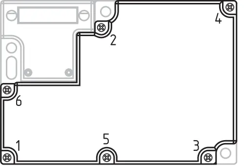
The interlock features three mounting holes for enclosure fixing. It is double-insulated, and the use of an earth wire is not authorized. The device must not be used as an end stop. Ensure the mounting position prevents the ingress of dirt and soiling. Unused actuator openings must be sealed with slot sealing plugs. The actuator must be permanently fitted to the safety guard and protected against displacement using tamperproof screws or similar measures.
Manual and emergency release
Manual release is performed by turning a triangular key (M5) by 180° to pull the locking bolt into the unlocking position. Emergency release (if equipped) uses an orange lever that must be turned to the stop to open the safety guard in an emergency. Emergency exit functions (if equipped) allow opening from within the hazardous area.
Electrical connection
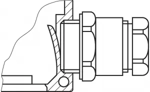
Electrical connection must be carried out by authorized personnel in a de-energized condition. Use appropriate cable glands with a suitable degree of protection. Ensure all plastic residues are removed from the switch compartment after preparing the cable entry. The tightening torque for the housing cover screws is 0.6 Nm.
Set-up and maintenance
The device is maintenance-free under correct installation and use. A regular visual inspection and functional test are recommended, including checking the fixation of the switch and actuator, verifying cable connections, and removing dust or soiling. Damaged or defective components must be replaced immediately.
Technical data
Key specifications include an IP67 protection rating, an operating temperature range of -30 °C to +60 °C, and a mechanical life of 1,000,000 operations. The device supports 24 VAC/DC or 110/230 VAC supply voltages depending on the model.
Disassembly and disposal
The safety switchgear must be disassembled only in a de-energized condition and disposed of in accordance with national prescriptions and legislations.
Manufacturer information
Schmersal
Practical help
Common problems
Safety guard cannot be opened
Check the power supply to the solenoid. If using a 'power to unlock' version, ensure the power is disconnected or the control signal is correct.
Manual release is jammed
Ensure there is no external pressure or jamming force acting on the actuator. The locking bolt must be free to move.
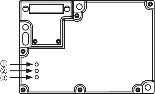
LED status is unclear
Refer to the LED status table on page 18 to verify the system condition (e.g., door closed, actuator inserted, locked/unlocked).
Before use
- Verify the supply voltage matches the device specifications (24 VAC/DC or 110/230 VAC).
- Ensure the actuator is permanently fitted to the safety guard.
- Check that all unused actuator openings are sealed with slot sealing plugs.
- Confirm the mounting position prevents dirt ingress.
- Ensure the electrical connection is performed by authorized personnel in a de-energized state.
Specs in practice
- Tightening torque
- 0.6 Nm is required for the cover screws to ensure proper sealing and mechanical integrity.
- Latching force
- The force required to hold the guard closed; standard is 5 N, optional R version is 30 N.
Images and diagrams
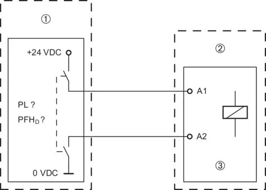
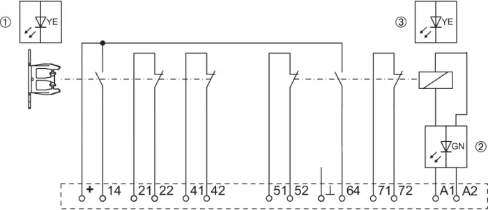
- Wiring diagrams illustrate the internal contact configuration for different versions (Power to unlock vs. Power to lock).
- The manual release diagram shows the use of a triangular key to retract the locking bolt.
- The emergency release diagram shows the orange lever operation.
Model compatibility
- Classified as a type 2 interlocking device according to EN ISO 14119.
- Not intended for private consumers.
- Requires evaluation of the safety chain in accordance with relevant standards.

Manual page author
Emily Carter
User documentation editor
Prepares concise manual descriptions and highlights the most useful setup, operation, and maintenance information for readers.