Furniture / Home Furnishing
Operating Instructions for Schmersal AZM 161CC-12 Safety Interlock
A comprehensive guide for the Schmersal AZM 161CC-12 safety interlock. This manual covers installation, electrical wiring, manual release procedures, emergency exit operation, and technical specifications for safe integration.
Table of contents
Manual images
Click an image to enlargeQuick guide from the manual
The Schmersal AZM 161CC-12 is a solenoid interlock designed to prevent movable safety guards from being opened before hazardous conditions have been eliminated. This device is intended for use by authorized qualified personnel only. Always ensure the device is installed according to relevant safety standards (EN ISO 14119) and that the operating instructions are accessible.
Product description
The AZM 161 series is classified as a type 2 interlocking device. It features various contact configurations (NO/NC) and latching forces. The device is available in 'Power to unlock' and 'Power to lock' versions. The 'Power to unlock' version is generally used for personal safety, as the guard can be opened immediately upon power failure or main switch activation.
Mounting
The interlock must be mounted using three holes. It is double-insulated and does not require an earth wire. The mounting position should prevent the ingress of dirt. The actuator must be permanently fitted to the safety guard using tamper-proof measures.
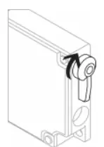
Manual release
For set-up and maintenance, a manual release is available. It is realized by turning a triangular key (M5) by 180°. After operation, the manual release must be secured with the included plastic cover.
Emergency release and exit
The emergency release (suffix -N) allows opening from outside the hazardous area in an emergency. The emergency exit (suffix -T, -TD, -TU) allows opening from within the hazardous area. These features must be clearly labeled and used only in emergencies.
Electrical connection
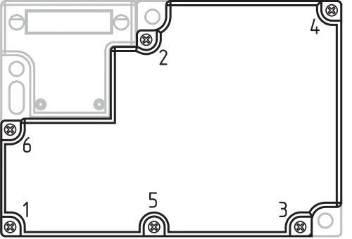
Electrical connections must be performed by authorized personnel in a de-energized state. Use appropriate cable glands. The tightening torque for the housing cover screws is 0.6 Nm. Ensure the tightening sequence is followed as illustrated in the manual.
Set-up and maintenance
The safety function must be tested regularly. Maintenance includes:
- Checking the fixation of the safety switch and actuator.
- Verifying the integrity of cable connections.
- Removing dust and soiling.
Damaged or defective components must be replaced immediately. Adequate measures must be taken to prevent tampering.
Disassembly and disposal
The device must be disassembled only in a de-energized state. Dispose of the switchgear in accordance with national regulations.
Manufacturer information
Schmersal
Practical help
Common problems
Safety guard cannot be opened
Check if the device is in 'Power to unlock' mode and if power is removed. If necessary, use the manual release.
Interlock not functioning
Verify the actuator is correctly inserted and the safety chain is designed according to relevant standards.
Cover screws loose
Ensure cover screws are tightened to 0.6 Nm in the specified sequence.
Before use
- Ensure installation is performed by authorized personnel.
- Verify the actuator is permanently fitted and protected against displacement.
- Check that all electrical connections are made while the device is de-energized.
- Confirm the tightening torque of the cover screws is 0.6 Nm.
- Test the safety function before commissioning the machine.
- Ensure the manual release is secured with the plastic cover after set-up.
Specs in practice
- Power to unlock
- The safety guard is locked when energized and opens when power is removed.
- Power to lock
- The safety guard is locked when power is applied.
Images and diagrams
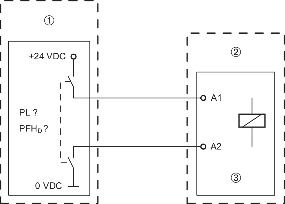
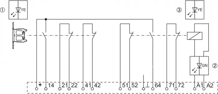
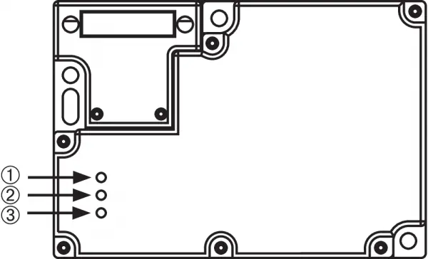
- Wiring diagrams show the internal contact configurations for different versions (Power to unlock/lock).
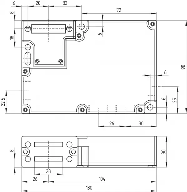
- Dimensions diagram provides the necessary spacing for mounting holes and overall device size.
- The cover screw sequence diagram illustrates the order for tightening the housing screws.
Model compatibility
- Not intended for private consumers.
- Must be used in accordance with EN ISO 14119.
- If multiple safety components are wired in series, the Performance Level may be reduced.

Manual page author
Michael Turner
Technical manual editor
Reviews PDF manuals for structure, safety notes, and practical product details so readers can find the right information quickly.