Industrial / Electrical
Safety Switch Schmersal AZ 16-12ZVRK-M20 User Manual
Comprehensive user manual for the Schmersal AZ 16-12ZVRK-M20 safety switch. Includes installation, electrical connection, maintenance, and technical specifications.
Table of contents
Quick guide from the manual
The Schmersal AZ 16-12ZVRK-M20 is a safety switch with a separate actuator designed for use with sliding, hinged, and removable safety guards. It is intended for industrial applications where hazardous situations must be terminated immediately upon opening the safety guard. All operations, including mounting and maintenance, must be performed by trained, authorized personnel.
Product description
The device is classified as a type 2 interlocking device according to EN ISO 14119. When the safety guard is opened, the NC contacts are positively opened, and the NO contacts are closed. The ordering code allows for various configurations, including different contact arrangements, latching forces, and connection types (cable entry or M12 connector).
Mounting
The switch can be mounted in any position, provided that the ingress of dirt and soiling into the used opening is avoided. Unused openings must be sealed with slot sealing plugs (available as an accessory). The actuator must be permanently fitted to the safety guard and protected against displacement using tamperproof screws, gluing, or by drilling the screw heads. The enclosure must not be used as an end stop.
Electrical connection
Electrical connections must only be performed by authorized personnel while the device is in a de-energized state. The contact labeling is located inside the wiring compartment. The conductor settle length is 6 mm. The switch is double-insulated, so a protective ground connector is not authorized. After wiring, ensure the compartment is free of dust and debris.
Set-up and maintenance
The safety function must be tested after installation. The device is generally maintenance-free, but a regular visual inspection and functional test are recommended, including:
- Checking for free movement of the actuating element.
- Checking cable entry and connections.
- Checking the switch enclosure for damage.
- Removing particles of dust and soiling.
Technical data
Key specifications include:
- Degree of protection: IP67
- Ambient temperature: -30 to +80 °C
- Switching principle: Slow action, positive break NC contact
- Safety contacts: 2
- Auxiliary contacts: 1
- Electrical ratings: 230 VAC / 4 A (AC-15) and 24 VDC / 4 A (DC-13)
Disassembly and disposal
The safety switchgear must be disassembled only in a de-energized condition. Disposal must be carried out in an appropriate manner in accordance with national prescriptions and legislations.
Manufacturer information
Schmersal
Practical help
Common problems
Safety guard not closing or switch not triggering
Check for free movement of the actuating element and ensure the actuator is correctly aligned with the switch.
Switch failure or intermittent operation
Verify electrical connections and cable entry integrity; ensure the wiring compartment is clean and free of debris.
Tampering concerns
Ensure adequate measures are taken to prevent tampering, such as using tamperproof screws or replacement actuators.
Before use
- Verify the safety switch is suitable for the specific application (sliding, hinged, or removable guards).
- Ensure the installation environment meets IP67 requirements.
- Check that the actuator is permanently fitted and protected against displacement.
- Verify that the electrical connection is performed by authorized personnel in a de-energized state.
- Confirm the wiring compartment is free of dust and debris after installation.
Specs in practice
- Positive break
- Ensures the NC contacts open when the safety guard is opened.
Images and diagrams
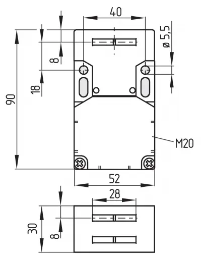
- Dimensions diagram shows the physical size (90x52x30mm) and mounting hole spacing.
- Front mounting diagram illustrates how to secure the switch to the panel.
- Contact options diagram displays the wiring configurations for different switch versions.
Model compatibility
- Classified as type 2 interlocking devices according to EN ISO 14119.
- Suitable for use up to Cat. 1 / PL c.
- Suitable for use up to Cat. 3 / PL d with 2-channel usage and fault exclusion.

Manual page author
David Miller
Documentation analyst
Organizes user manual content into clear summaries, with attention to model details, product context, and everyday usability.