Furniture / Home Furnishing
Operating Instructions for Schmersal AZM 161CC-12 Solenoid Interlock
Quick guide for the Schmersal AZM 161CC-12 solenoid interlock. Includes installation, electrical connection, manual release procedures, and technical specifications.
Table of contents
Manual images
Click an image to enlargeQuick guide from the manual
The Schmersal AZM 161CC-12 is a solenoid interlock designed to prevent movable safety guards from being opened before hazardous conditions are eliminated. This device is intended for use by authorized qualified personnel only. Ensure the power supply matches the device rating (24 VAC/DC or 110/230 VAC) and that the safety chain is designed according to relevant standards.
Product Description
The solenoid interlock is classified as a type 2 interlocking device according to EN ISO 14119. It is not intended for private consumers. The device features various contact configurations and options for manual release and emergency exit, depending on the specific ordering code.
Mounting
The device is fixed using three mounting holes. The solenoid interlock is double insulated; the use of an earth wire is not authorized. The mounting position must be chosen to avoid the ingress of dirt and soiling. Unused actuator openings must be sealed with slot sealing plugs. The actuator must be permanently fitted to the safety guard and protected against displacement.
Manual and Emergency Release
Manual release is performed by turning the triangular key by 180 degrees. Emergency release (ordering suffix -N) is for use only in emergencies and must be clearly labeled. Emergency exit (T, TD, TU versions) allows for actuation from within the hazardous area.
Electrical Connection
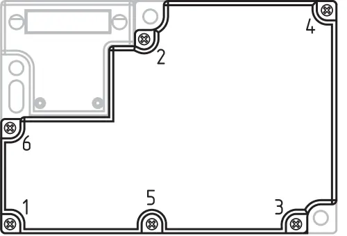
Electrical connection must be carried out by authorized personnel in a de-energized condition. Appropriate cable glands with a suitable degree of protection must be used. Remove the walls of the mounting holes by inserting the cable entry and ensure all plastic residues are removed from the switch compartment. The tightening torque for the housing cover screws is 0.6 Nm.
Set-up and Maintenance
A regular visual inspection and functional test are recommended, including checking the fixation of the safety switch and actuator, verifying the integrity of cable connections, and removing dust or soiling. Damaged or defective components must be replaced immediately.
Technical Data
- Protection Class: IP67
- Ambient Temperature: -30 to +60 °C
- Nominal Control Voltage: 24 VAC/DC or 110/230 VAC
- Switching Principle: Slow action, positive break NC contact
- Max. Switching Frequency: 1,000 /h
Disassembly and Disposal
The safety switchgear must be disassembled in a de-energized condition only. Dispose of the device in an appropriate manner in accordance with national prescriptions and legislations.
Manufacturer information
Schmersal
Practical help
Common problems
Safety guard will not lock
Check actuator alignment and ensure the latching force is appropriate for the application.
Interlock cannot be opened
Verify power supply status (for power-to-unlock versions) or use the manual release mechanism if authorized.
LED indicator not lit
Check the power supply connection and ensure the wiring matches the specific contact configuration.
Before use
- Verify the power supply voltage matches the device specifications (24 VAC/DC or 110/230 VAC).
- Ensure the actuator is correctly aligned and permanently fitted to the safety guard.
- Check that the mounting position prevents the ingress of dirt and debris.
- Confirm the safety chain is designed according to relevant safety standards.
- Ensure all electrical connections are made by authorized personnel while the device is de-energized.
Specs in practice
- Power to unlock
- The safety guard can be opened immediately upon failure of the power supply.
- Power to lock
- The safety guard remains locked upon failure of the power supply.
Images and diagrams
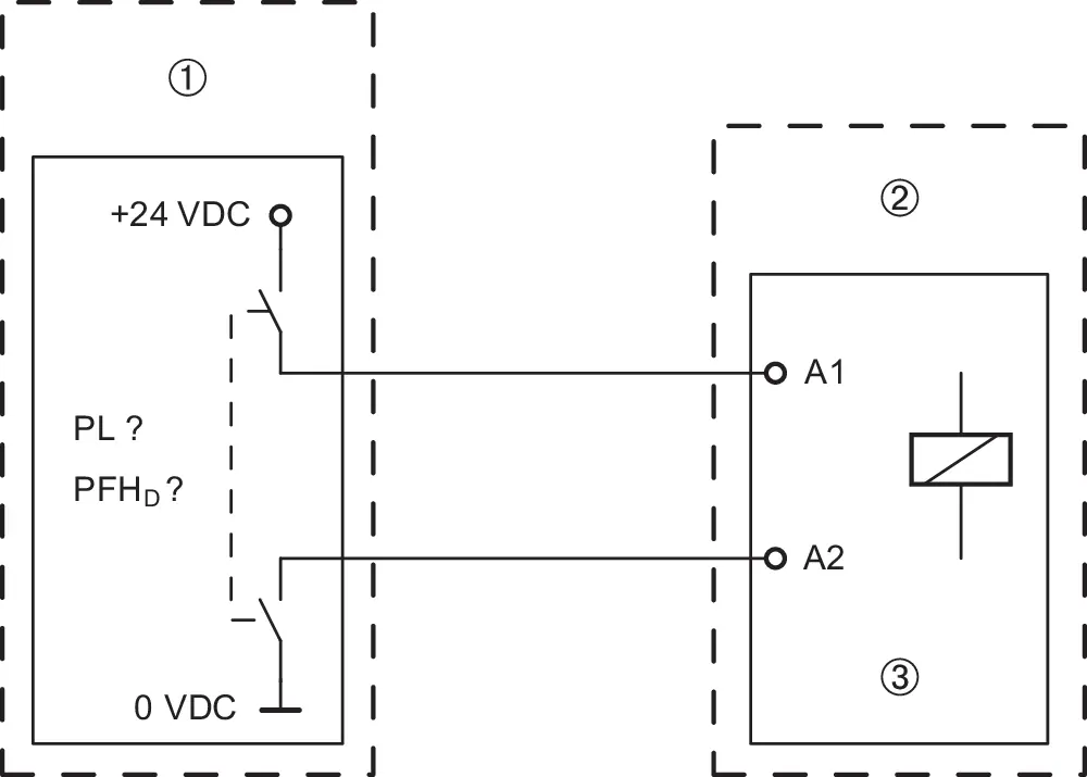
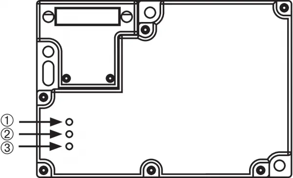
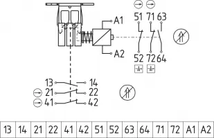
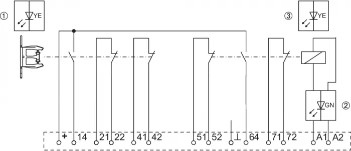
- Wiring diagrams illustrate the contact configurations for different versions (Power to unlock vs. Power to lock).
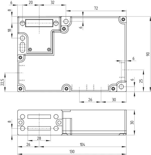
- Dimensions drawing provides the necessary spacing for mounting holes and overall device size.
- Tightening sequence diagram indicates the specific order for securing the housing cover screws.
Model compatibility
- Classified as a type 2 interlocking device according to EN ISO 14119.
- Not intended for use by private consumers.
- Must be used with a suitable logic unit for safety classification.

Manual page author
David Miller
Documentation analyst
Organizes user manual content into clear summaries, with attention to model details, product context, and everyday usability.