Industrial / Control Switches
Operating Instructions for Schmersal AZM 161CC Solenoid Interlock Switch
Quick guide for the Schmersal AZM 161CC solenoid interlock switch. Includes installation, wiring, manual release, emergency exit procedures, and technical specifications.
Table of contents
Manual images
Click an image to enlargeQuick guide from the manual
This document provides essential information for the mounting, set-up, and commissioning of the Schmersal AZM 161CC solenoid interlock switch. All operations must be performed by authorized, qualified personnel. The device is designed to prevent safety guards from being opened before hazardous conditions are eliminated.
Product Description
The AZM 161CC is a type 2 interlocking device according to EN ISO 14119. It is available in various configurations, including power-to-unlock and power-to-lock principles. The ordering code determines specific features such as connection type (screw, cage clamps, or M12 connector), latching force, and manual release options.
Mounting
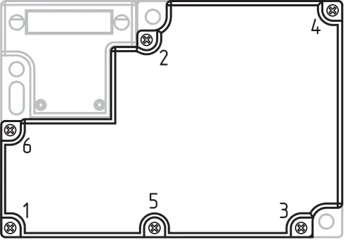
The switch features three mounting holes for enclosure fixing. It is double-insulated and does not require an earth wire. The mounting position should be chosen to prevent the ingress of dirt. The actuator must be permanently fitted to the safety guard and protected against displacement. Unused actuator openings must be sealed with slot sealing plugs.
Manual Release
Manual release is performed by turning the triangular key by 180 degrees. This pulls the locking bolt into the unlocking position. After operation, the manual release must be secured by installing the included plastic cover.
Emergency Release and Exit
Emergency release (suffix -N) allows opening from outside the hazardous area. Emergency exit (suffix -T, -TD, -TU) allows opening from within the hazardous area. These features should only be used in emergencies.
Electrical Connection
Electrical connection must be carried out by authorized personnel in a de-energized condition. Appropriate cable glands must be used. The conductor settle length is 5-6 mm for cage clamps and 7 mm for screw terminals. After connection, clean the inside of the switch and refit the housing cover, tightening screws to 0.6 Nm in the specified sequence.
Set-up and Maintenance
The safety function must be tested regularly. Recommended maintenance includes checking the fixation of the switch and actuator, verifying the integrity of cable connections, and removing dust or soiling. Damaged or defective components must be replaced immediately.
Technical Data
The device operates within a temperature range of -30 to +60 degrees Celsius and has an IP67 protection rating. It is available for 24 VAC/DC or 110/230 VAC power supplies. The mechanical life is at least 1,000,000 operations.
Manufacturer information
Schmersal
Practical help
Common problems
Safety guard cannot be opened
Check if power is supplied (for power-to-unlock) or if power is cut (for power-to-lock). Use the manual release if necessary.
Interlock not functioning
Verify wiring connections and ensure the actuator is correctly inserted and aligned.
Damaged component
Replace the component immediately; do not attempt arbitrary repairs or modifications.
Before use
- Ensure installation is performed by authorized qualified personnel.
- Verify that the safety guard is protected against displacement.
- Check that the actuator is permanently fitted.
- Ensure the device is de-energized before electrical connection.
- Verify that cable glands are appropriate for the protection degree.
- Check that the tightening sequence for cover screws is followed.
Specs in practice
- Power to unlock
- Safety guard is locked when energized; unlocks when power is removed.
- Power to lock
- Safety guard is locked when de-energized; locks when power is applied.
Images and diagrams
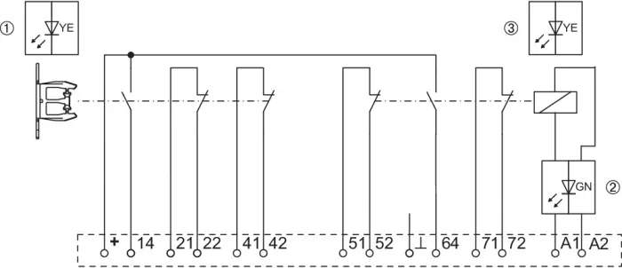
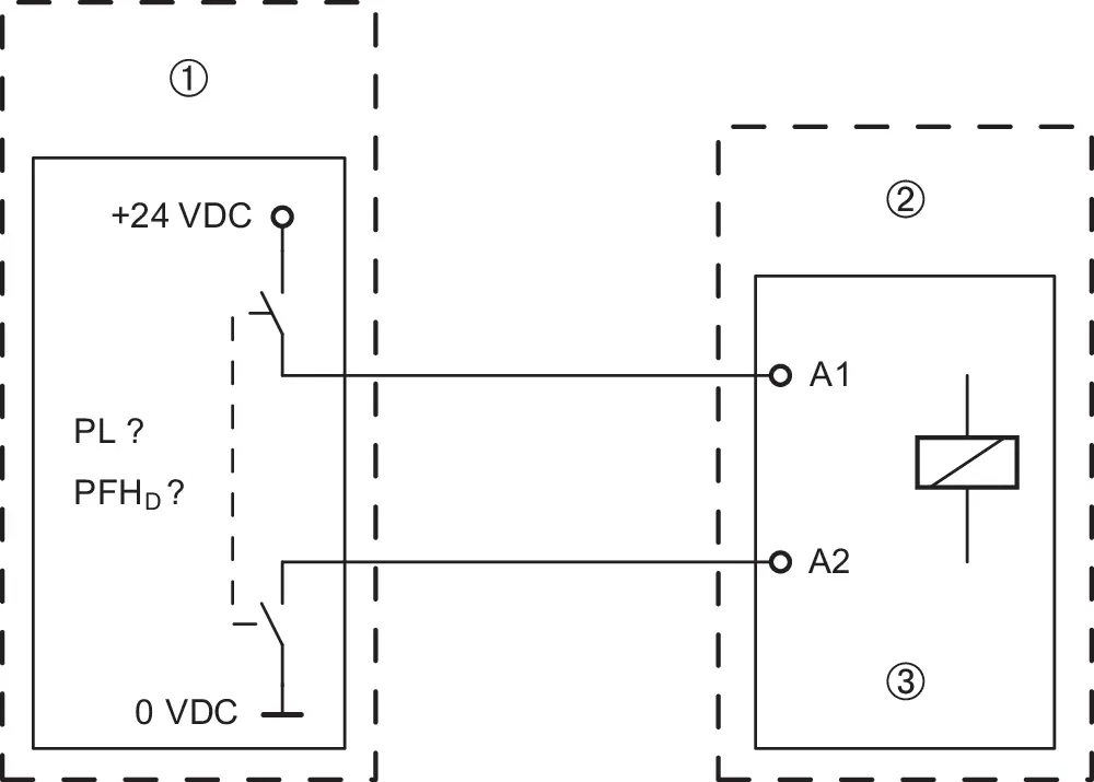
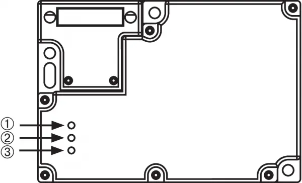
- Wiring diagrams show the internal contact configuration for different versions.
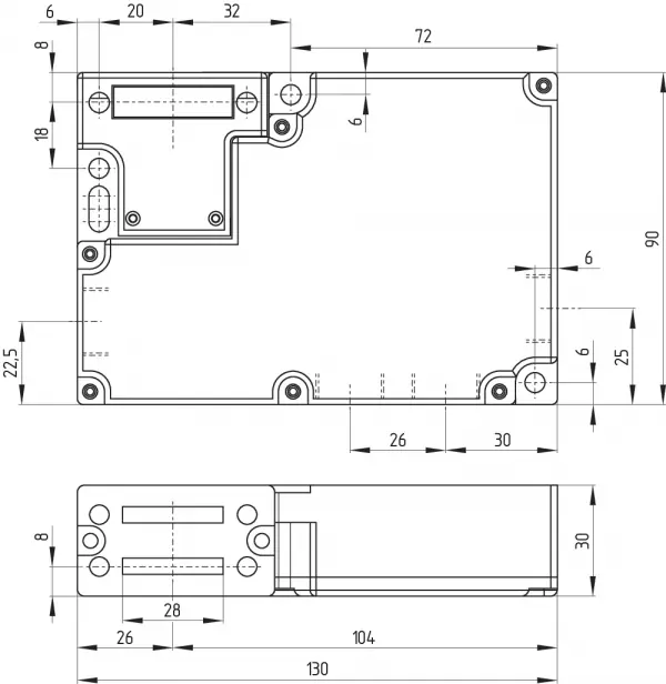
- Dimensions diagram provides mounting hole spacing and overall size.
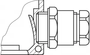
- Manual release diagram shows the triangular key operation.
Model compatibility
- Classified as type 2 interlocking devices according to EN ISO 14119.
- Not intended for private consumers.
- Must be used in accordance with the versions listed in the ordering code.

Manual page author
Emily Carter
User documentation editor
Prepares concise manual descriptions and highlights the most useful setup, operation, and maintenance information for readers.