Industrial / Access Control
Installation Guide for SDC 1091ADMR Concealed Mortise Bolt Lock
Installation and wiring guide for the SDC 1091ADMR Concealed Mortise Bolt Lock. Includes frame preparation, cylinder reversal instructions, and dual-voltage wiring diagrams.
Table of contents
Manual images
Click an image to enlargeImportant Installation Information
The SDC 1091ADMR is a concealed mortise bolt lock with mechanical release fail-safe. This guide provides instructions for frame preparation, cylinder reversal, and electrical wiring. Note that a standard straight cam ILCO (863G) or equivalent cylinder is required but not included with the unit.
Technical Data
- Face Plate: 10-1/2" x 1-1/2" x 1/8"
- Strike: 4" x 1-1/2" x 1/8"
- Bolt: 5/8" diameter, stainless steel
- Bolt Throw: 3/4"
- Backset: .865"
- Dual Voltage Solenoid: 12VDC @ 0.9A (max) or 24VDC @ 0.45A (max)
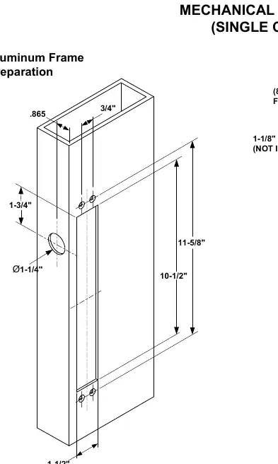
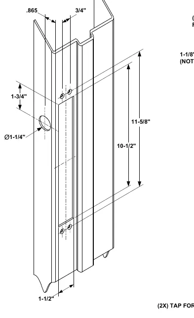
Frame and Door Preparation
The installation requires precise cutting of the door and frame. Ensure the frame is prepared according to the specific type (Aluminum or Hollow Metal). The face plate and strike require specific cutouts as detailed in the diagrams. Ensure the mounting tabs are tapped for #10-32 screws.
Reversing the Cylinder
If the cylinder needs to be reversed, follow these steps:
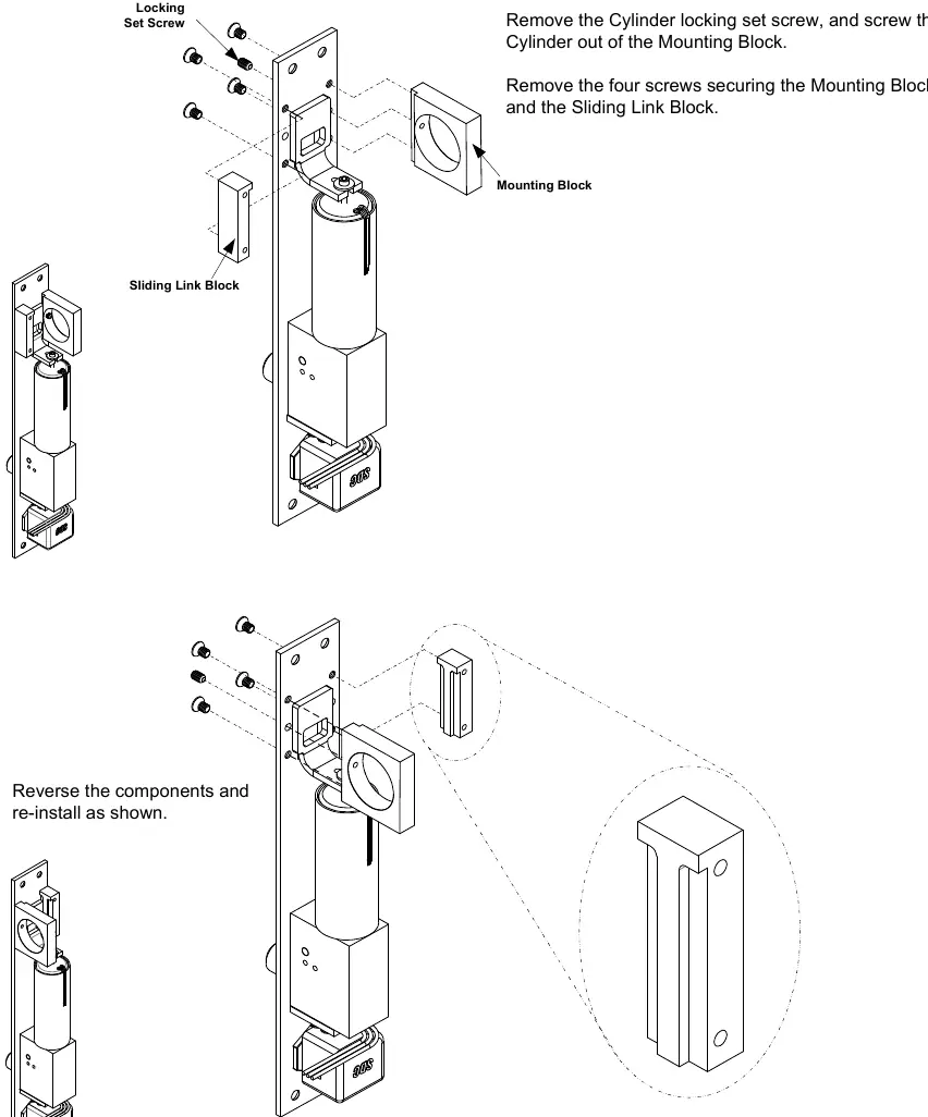
- Remove the cylinder locking set screw and unscrew the cylinder from the mounting block.
- Remove the four screws securing the mounting block and the sliding link block.
- Reverse the components and re-install them as shown in the diagram.
- Ensure the sliding link block is aligned properly before securing the screws.
Lock Wiring
The unit uses a provided pigtail connector for power. Select the appropriate configuration based on your power supply:
- 24VDC Configuration: Connect the power input to the red and white wires as indicated in the wiring diagram. Cap unused wires.
- 12VDC Configuration: Connect the power input to the red and white wires as indicated in the wiring diagram.
Ensure the access control or push button (N/C) is wired correctly to the common (COM) and N/C terminals.
Optional Sensors
The unit may include optional sensors:
- Bolt Position Sensor (BPS-Magnetic): Indicates if the bolt is locked or unlocked (5 Watt).
- Door Position Switch (DPS-Mechanical): Indicates if the door is opened or closed (4A @ 30VDC Resistive).
Practical help
Common problems
Bolt not engaging or locking
Check the alignment of the strike and bolt. Ensure the door is fully closed and the frame cutout is accurate.
Incorrect voltage configuration
Verify the wiring against the 12VDC or 24VDC configuration diagrams. Ensure the pigtail connector is wired correctly.
Before use
- Verify the frame type (Aluminum or Hollow Metal) and follow the corresponding preparation steps.
- Ensure you have a standard straight cam ILCO (863G) or equivalent cylinder (not included).
- Check that the door and frame are prepared according to the specified dimensions (10-1/2" x 1-1/2").
- Confirm the power supply matches the 12VDC or 24VDC solenoid configuration.
- Ensure all unused wires are capped to prevent short circuits.
Specs in practice
- Dual Voltage Solenoid
- Supports both 12VDC (0.9A) and 24VDC (0.45A) power inputs.
Images and diagrams
- Wiring diagrams show how to connect the pigtail connector for 12VDC or 24VDC power.
- Preparation diagrams illustrate the required cutouts for the face plate and strike in both aluminum and hollow metal frames.
Model compatibility
- Requires a standard straight cam ILCO (863G) or equivalent cylinder (not included).

Manual page author
David Miller
Documentation analyst
Organizes user manual content into clear summaries, with attention to model details, product context, and everyday usability.