Home / Security
Installation Instructions for SDC 1000R and 1000V Electric Latch Retraction Kit
A comprehensive installation guide for the SDC LR100DHK Electric Latch Retraction Kit. Includes step-by-step mounting procedures, wiring specifications, and specific retrofitting instructions for 1000R and 1000V models.
Table of contents
Manual images
Click an image to enlargeQuick Installation Guide
The SDC LR100DHK kit is designed to retrofit exit devices for electric latch retraction. Key requirements include verifying space for the assembly, especially on 42" or 48" devices modified to fit smaller openings. Ensure you have a drill with a .107" bit and a 6-32 tap before beginning. The unit operates on 24VDC.
Installation Preparation
Before starting the installation, verify the distance from the end of the touchpad to the end rail. If the device has been modified to fit a 36" or smaller opening, there may not be sufficient space for the standard E.L.R. assembly. Consult the factory if you are unsure about compatibility.
Mounting the Adapter
Steps:
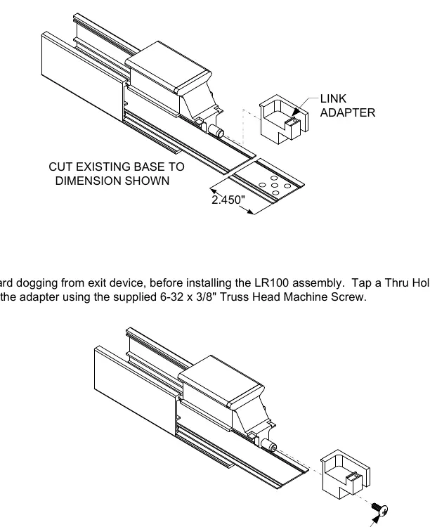
- Remove and discard the existing dogging from the exit device.
- Place the adapter over the device to use as a template.
- Drill a .107" diameter thru-hole.
- Tap the hole to accept a 6-32 thread.
- Attach the adapter using the supplied 6-32 x 3/8" Truss Head Machine Screw.
- Cut the existing base to the dimension shown in the diagram (2.450").
Installing the E.L.R. Assembly
Steps:
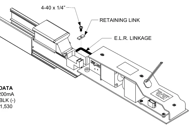
- Place the E.L.R. linkage inside the adapter.
- Secure it in place using the supplied retaining link and 4-40 x 1/4" Pan Head Screw.
- Power the unit to cause the E.L.R. to pull towards the exit device.
- Depress the push pad to position the E.L.R. into the working position.
- Pull back on the E.L.R. assembly to remove any slack.
- Fasten the set screws on the assembly to secure the kit into the device.
- Release the push pad and verify operation by de-energizing and re-energizing the kit to ensure proper latch retraction.
Electrical Data
The unit requires 24VDC power. The wiring polarity is as follows:
- Red: (+)
- Black: (-)
- Current Draw: 700/200mA
Retro-Fitting Vertical Rod Devices
To ensure proper alignment when installing into a vertical rod device:
- Disconnect the vertical rods from the device.
- Install the electric latch assembly as described above.
- Energize the unit so the push pad is dogged down; this allows for proper alignment of the vertical rods.
- Reconnect the vertical rods to the device and make necessary adjustments.
Practical help
Common problems
Insufficient space for E.L.R. assembly
42" or 48" exit devices modified to fit 36" or smaller openings may not have enough space. Always verify the distance from the end of the touchpad to the end rail before installation.
Vertical rod misalignment
Disconnect vertical rods before installing the ELR. Energize the ELR to dog down the push pad before reconnecting the rods to ensure proper alignment.
Before use
- Verify exit device size and available space.
- Remove existing dogging from the exit device.
- Ensure 24VDC power supply is available.
- Prepare a drill with a .107" bit.
- Prepare a 6-32 tap for the mounting hole.
Images and diagrams
- Adapter mounting: Shows the cut dimension (2.450") and the location for the 6-32 screw.
- Linkage installation: Illustrates the placement of the retaining link and 4-40 screw.
Model compatibility
- Compatible with SDC 1000R and 1000V models.
- Retrofit note: Check space on modified 42"/48" devices.

Manual page author
Michael Turner
Technical manual editor
Reviews PDF manuals for structure, safety notes, and practical product details so readers can find the right information quickly.