Industrial / Door Hardware
SDC 1091AIDDMR1 Concealed Mortise Bolt Lock Installation Instructions
Installation and wiring guide for the SDC 1091AIDDMR1 Concealed Mortise Bolt Lock. Includes door and frame preparation dimensions, 12V/24V wiring diagrams, and sensor configuration.
Table of contents
Manual images
Click an image to enlargeQuick guide from the manual
The SDC 1091AIDDMR1 is a concealed mortise bolt lock with mechanical release fail-safe. This document provides the necessary dimensions for door and frame preparation, wiring configurations for 12VDC or 24VDC power, and sensor setup instructions. Ensure you use a standard straight cam ILCO (863G) or equivalent cylinder.
Door and frame preparation
Proper preparation is critical for the installation of the mortise bolt lock. Refer to the provided diagrams for exact measurements:
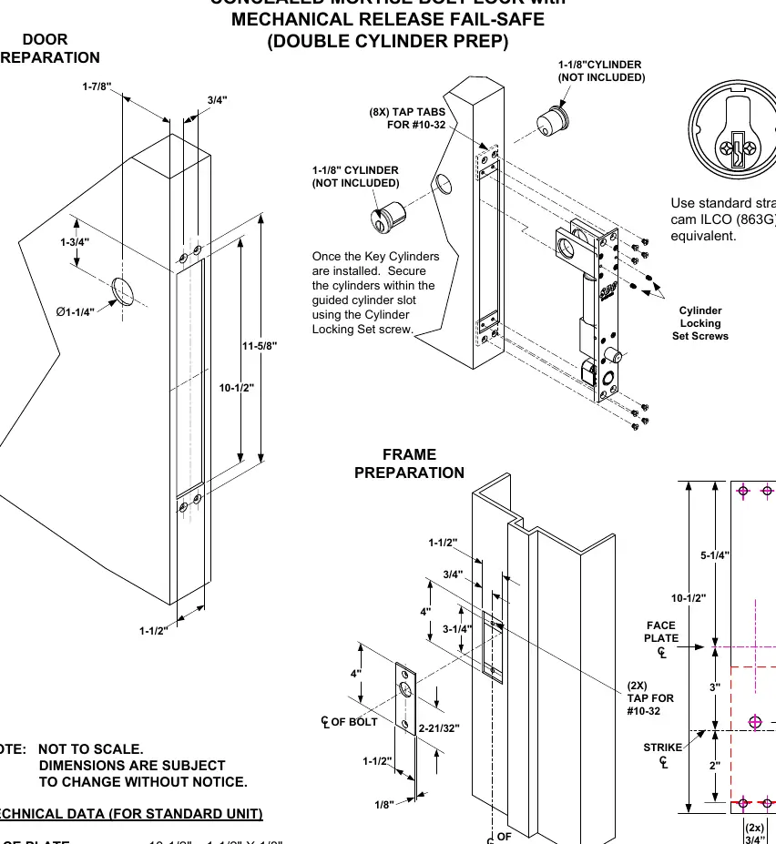
- Door Preparation: Requires a cutout for the bolt mechanism. The backset is 1-7/8 inches.
- Frame Preparation: Requires a cutout for the strike plate. Ensure the strike plate center line aligns with the bolt center line.
- Tap Tabs: Use (8x) tap tabs for #10-32 screws for the lock installation and (2x) tap tabs for the strike plate.
Cylinder installation
Once the key cylinders are installed, secure them within the guided cylinder slot using the Cylinder Locking Set screw. Ensure the cylinder cam is compatible (standard straight cam ILCO 863G or equivalent).
Lock wiring
The lock supports both 12VDC and 24VDC configurations using the provided pigtail connector. Cap any unused wires.
- 24VDC Configuration: Connect power input to the pigtail connector according to the diagram.
- 12VDC Configuration: Connect power input to the pigtail connector according to the diagram.
- Access Control: Connect the Access Control or Push Button (N/C) to the N/C and COM terminals.
Electrical data
- 12VDC Solenoid: 0.9 Amp (Max) Continuous Duty.
- 24VDC Solenoid: 0.45 Amp (Max) Continuous Duty.
- Bolt Position Sensor (BPS-Magnetic): Indicates bolt locked or unlocked (5 Watt).
- Door Position Switch (DPS-Mechanical): Indicates door opened or closed (4A @ 30VDC Resistive).
BPS/DPS configuration
The unit features optional sensors. The wiring color codes are as follows:
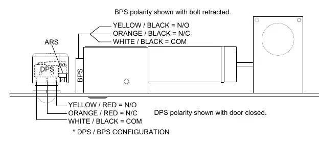
- BPS (Bolt Position Sensor): Yellow/Black = N/O, Orange/Black = N/C, White/Black = COM.
- DPS (Door Position Switch): Yellow/Red = N/O, Orange/Red = N/C, White/Black = COM.
Note: When both options are ordered, the Common is shared.
Practical help
Common problems
Incorrect voltage configuration
Ensure the pigtail connector wiring matches the 12VDC or 24VDC power source requirements.
Bolt not locking or unlocking
Verify the BPS sensor status. 'B' indicates the bolt is locked or unlocked.
Door status not detected
Verify the DPS sensor wiring. 'D' indicates the door is opened or closed.
Before use
- Verify the backset is 1-7/8 inches.
- Ensure the door and frame are prepared according to the provided dimensions.
- Confirm the power supply is either 12VDC or 24VDC.
- Use a standard straight cam ILCO (863G) or equivalent cylinder.
- Ensure all unused wires are capped.
Specs in practice
- 12VDC Solenoid
- Requires 0.9 Amp (Max) Continuous Duty.
- 24VDC Solenoid
- Requires 0.45 Amp (Max) Continuous Duty.
Images and diagrams
- Door Preparation: Shows the required cutouts and dimensions for the bolt lock installation.
- Frame Preparation: Shows the required cutouts and dimensions for the strike plate.
- Wiring Diagram: Illustrates the pigtail connector wiring for 12VDC and 24VDC power inputs.
- BPS/DPS Configuration: Details the color-coded wiring for the optional Bolt Position Sensor and Door Position Switch.
Model compatibility
- Requires standard straight cam ILCO (863G) or equivalent cylinder.
- Compatible with 12VDC or 24VDC power systems.

Manual page author
Michael Turner
Technical manual editor
Reviews PDF manuals for structure, safety notes, and practical product details so readers can find the right information quickly.