Industrial / Sensor Accessories
User Manual for BEA FLY Request-to-Exit Sensor
Quick guide for the BEA FLY and FLY ERT request-to-exit sensors. Includes installation steps, wiring diagrams, DIP switch settings, and troubleshooting tips.
Table of contents
Manual images
Click an image to enlargeQuick guide from the manual
The BEA FLY and FLY ERT are request-to-exit sensors designed for access control. Important: These sensors are not recommended for activation on pedestrian automatic doors because the passive infrared technology detects temperature changes (body heat) and will not recognize inanimate objects like shopping carts or gurneys. Ensure all wiring is checked before powering up and that the door control system is properly grounded.
Description
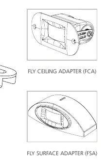
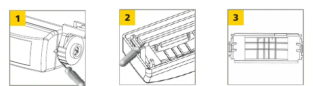
The sensor consists of a lens (with mask inside) and a housing. It can be used with optional adapters: the FLY Ceiling Adapter (FCA) or the FLY Surface Adapter (FSA).
Precautions
- Shut off all power to the header before wiring.
- Only trained and qualified personnel should install and set up the sensor.
- Always test the proper operation of the installation before leaving the premises.
- Do not attempt internal repairs; unauthorized disassembly voids the warranty.
- Ensure compliance with safety standards such as ANSI A156.10.
Preparing the Sensor
The sensor can be customized using the mask and DIP switches:
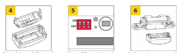
- Masking: To adjust the sensing field, remove segments of the mask using a diagonal cutter. You can choose between Full, Asymmetric, or Shorter Depth detection patterns. If using the mask, cut at least one segment to allow detection.
- DIP Switches: Adjust settings based on your application:
- 1 (Sensitivity): ON = high, OFF = low.
- 2 (Relay Output): ON = passive output (relay contact open during detection), OFF = active output (relay contact closed during detection).
- 3 (Hold Time): For FLY: ON = 2 sec, OFF = 0.5 sec. For FLY ERT: ON = 30 sec, OFF = 15 sec.
Mounting & Wiring
- Attach the template to the frame above the door.
- Drill holes and pass the cable through the template.
- Place the sensor on the template and attach using the provided screws.
- Connect the sensor cable to the unit. Input power is not polarity-sensitive.
Wiring Table:
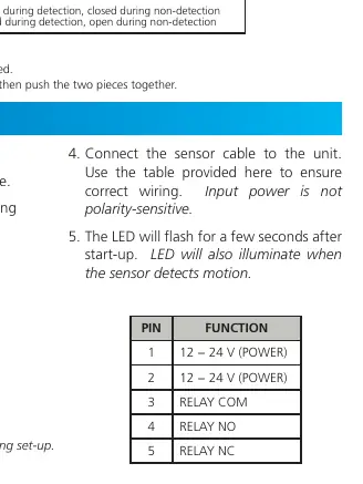
- Pin 1: 12 - 24 V (POWER)
- Pin 2: 12 - 24 V (POWER)
- Pin 3: RELAY COM
- Pin 4: RELAY NO
- Pin 5: RELAY NC
The LED will flash for a few seconds after start-up and will illuminate when motion is detected.
Troubleshooting
- Door will not unlock / LED does not illuminate: Check power supply and supplied voltage.
- Lock does not release upon detection, but LED illuminates: Check for incorrect relay output (change #2 DIP switch position) or incorrect wiring.
- Size of detection field does not meet requirements: Adjust the masking lens by cutting a new one to meet the required size.
Technical Specifications
- Technology: Passive infrared with microprocessor.
- Mounting Height: 10' max (recommended 6'6" – 8'0").
- Power Supply: 12 – 24 VAC or 12 – 24 VDC.
- Relay Contact Rating: 1 A / 75 VDC or 50 VAC.
- Operating Temperature: -22 to 140 °F (-30 to 55 °C).
- Cable: 9' four-conductor cable with 5-pin connector.
For technical support, contact 1-800-523-2462 or visit www.BEAsensors.com.
Official resources from the manual
Manufacturer information
BEA Sensors
Practical help
Common problems
Door will not unlock and LED does not illuminate
Check the power supply and verify the supplied voltage.
Lock does not release upon detection, but LED illuminates
Verify wiring or change the #2 DIP switch position to correct the relay output.
Detection field size is incorrect
Cut a new masking lens to meet the required detection field size.
Before use
- Shut off all power to the header before wiring.
- Ensure the door control system and header cover are correctly grounded.
- Verify that the installation environment is clean and safe.
- Ensure qualified personnel are performing the installation.
- Test the operation of the installation before leaving the premises.
Specs in practice
- Power Supply
- 12-24 VAC or 12-24 VDC; input is not polarity-sensitive.
- Relay Output
- Passive (open during detection) or Active (closed during detection) configurable via DIP switch 2.
Images and diagrams
- Masking patterns: Remove gray portions of the mask to achieve Full, Asymmetric, or Shorter Depth detection fields.
- Wiring: 5-pin connector layout defines power (Pins 1-2) and relay contacts (Pins 3-5).
Model compatibility
- Not recommended for activation on pedestrian automatic doors.
- Passive infrared technology detects temperature changes; will not detect inanimate objects like shopping carts or gurneys.

Manual page author
Michael Turner
Technical manual editor
Reviews PDF manuals for structure, safety notes, and practical product details so readers can find the right information quickly.