Industrial / Door Hardware
Installation Guide for SDC 1091AIWD Fail-Safe Concealed Mortise Bolt Lock
Comprehensive installation and wiring guide for the SDC 1091AIWD and 1091AIWDDL Fail-Safe Concealed Mortise Bolt Lock. Includes mounting instructions for horizontal and vertical applications, solenoid voltage configuration, PR-1000...
Table of contents
Manual images
Click an image to enlargeQuick Guide for Installation
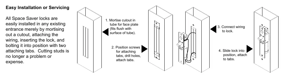
The SDC 1091AIWD is a concealed mortise bolt lock designed for easy installation in existing entrances. The process involves mortising a cutout, attaching the wiring, inserting the lock, and securing it with two attaching tabs. The unit includes a PR-1000 Power Regulator to reduce power consumption and heat, which is recommended for optimal performance.
Installation Instructions
Overhead Installation (Horizontal):
- Examine the top rail of the door to locate the strike plate position.
- Mark the door for the end of the strike plate and make a corresponding mark on the header.
- Locate the center line of the door thickness on the header and attach the adhesive cutout template.
- Center punch the tab-mounting screw locations, counter-sink for #10 screws, and saw or rout out the cutout area.
Sidejamb Installation (Vertical):
- Examine the lock stile jamb for the point nearest the center of the door height.
- Mark the door stile horizontal for the top end of the strike plate and make a corresponding mark on the jamb.
- Attach the adhesive cutout template to the jamb, aligning the top of the cutout with the horizontal mark.
- Center punch the tab-mounting screw locations, counter-sink for #10 screws, and saw or rout the cutout.
Finalizing Installation:
- Attach the mounting tabs inside the cavity.
- Connect power supply leads to the lock leads.
- Insert the lock into the cutout. When installed horizontally, the bolt end must be nearest the lock stile. When installed vertically, the bolt must be at the top end of the cutout.
- Secure the lock with #10-32 machine screws.
- Use the strike plate as a template to mark and drill screw holes, then mortise and attach the strike.
Auto Relock Switch (ARS) Adjustment
The Automatic Relock Switch (ARS) is factory-set for a 1/8 inch clearance between the top of the door and the transom bar or head jamb. If there is a wider gap, you can compensate for it:
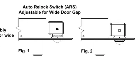
- Loosen the lock nut on the switch assembly.
- Turn the assembly clockwise to adjust for a wider door gap.
- Tighten the lock nut once the adjustment is satisfactory.
Wiring and Power Configuration
The PR-1000 Power Regulator is included to reduce heat and increase solenoid life. DC voltage is recommended for improved heat reduction.
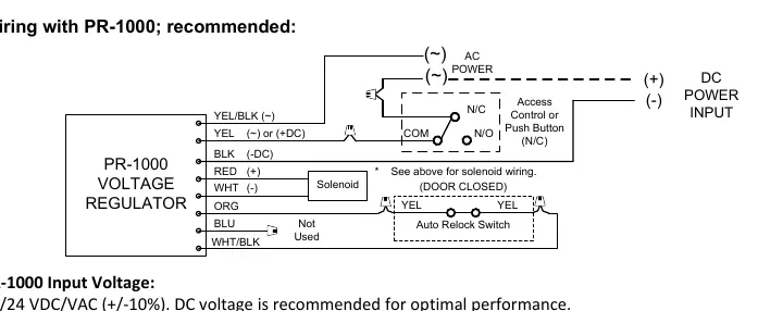
- Solenoid Voltage: Configure for 12VDC (900mA max) or 24VDC (450mA max) as indicated in the wiring diagrams.
- Wiring with PR-1000: Connect the PR-1000 between the power source and the lock. The regulator accepts 12/24 VDC/VAC (+/-10%).
- Wiring without PR-1000: Connect the solenoid directly to the power source and access control switch, ensuring correct voltage polarity.
Troubleshooting
- Bolt does not project: Check voltage and alignment of the strike.
- Bolt projects but chatters: Voltage is too low.
- Bolt will not retract: Strike is mis-aligned.
Technical Data
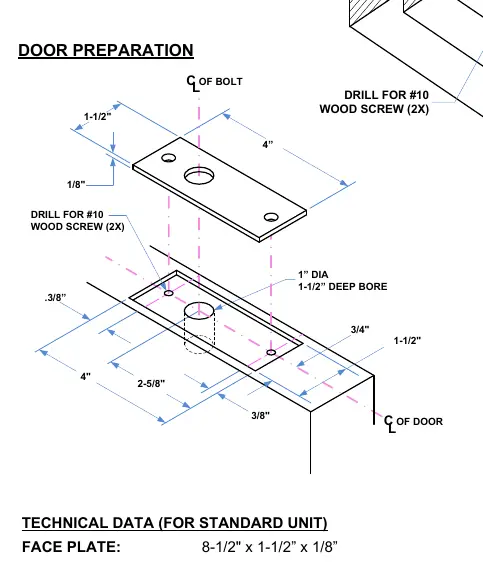
- Face Plate: 8-1/2 inch x 1-1/2 inch x 1/8 inch.
- Strike: 4 inch x 1-1/2 inch x 1/8 inch.
- Bolt: 5/8 inch diameter, solid stainless steel.
- Bolt Throw: 3/4 inch.
- PR-1000 Module: 3-3/4 inch x 1-1/4 inch x 1/2 inch.
Practical help
Common problems
Bolt does not project
Check voltage and alignment of the strike.
Bolt projects but chatters
Voltage is too low; ensure power supply meets requirements.
Bolt will not retract
Strike is mis-aligned; adjust position.
Before use
- Verify door type and frame suitability.
- Ensure power supply is 12VDC or 24VDC.
- Check for inclusion of PR-1000 Power Regulator.
- Measure clearance for ARS (factory set for 1/8 inch).
- Ensure tools for mortising and drilling are available.
Images and diagrams
- Wiring diagrams illustrate connections for both 12V and 24V configurations.
- ARS adjustment diagram shows the nut and assembly rotation for wide door gaps.
- Installation steps diagram shows the sequence of mortising, wiring, and sliding the lock into position.
Model compatibility
- Compatible with PR-1000 Power Regulator (included).
- Suitable for both overhead horizontal and sidejamb vertical installations.

Manual page author
David Miller
Documentation analyst
Organizes user manual content into clear summaries, with attention to model details, product context, and everyday usability.