Home / Security
Quick Start Guide for Security Brands Ascent M1 Access Controller
Quick start guide for the Security Brands Ascent M1 cellular gate and door access controller. Includes installation, wiring diagrams for power, relays, Wiegand devices, and status inputs.
Table of contents
Manual images
Click an image to enlargeQuick Start Information
The Ascent M1 is a cellular accessory for gates and doors. This document provides essential installation and wiring instructions. Important: The unit will not function until the activation process is complete. Please follow the separate Activation Guide to set up your account. An emergency egress or primary entry mechanism should always be used in conjunction with this unit.
Unpacking and Mounting
Ensure all items are present before beginning installation:
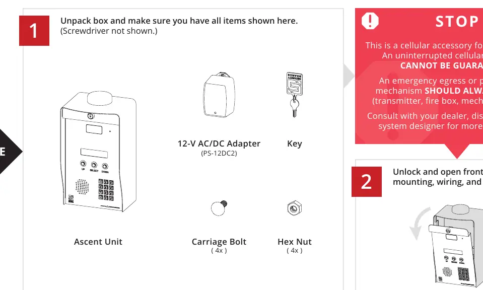
- Ascent Unit
- 12-V AC/DC Adapter (PS-12DC2)
- Key
- 4x Carriage Bolts
- 4x Hex Nuts
Mounting Instructions:
- We recommend mounting the unit on a gooseneck pedestal using the included hardware.
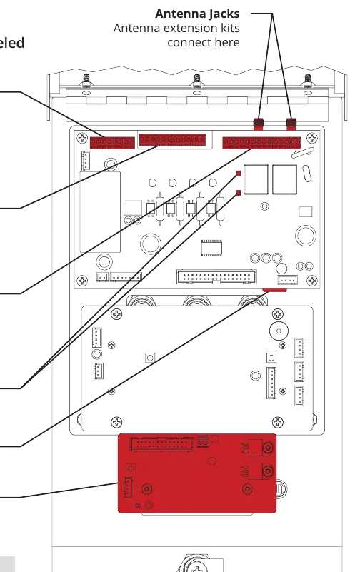
- If using alternate mounting, the 4G LTE Antenna Extension Kit (Model 16-ANTX-1) must be purchased and installed to prevent signal loss.
- Use all four carriage bolts when mounting.
- Leave the hockey puck antenna in place even if using an extension.
- Seal all openings in the enclosure to prevent damage.
Wiring Overview
Feed wires through the back of the unit and connect them using the included screwdriver. Do not use excessive force. Additional wiring diagrams are available on pages 4-6 of the manual.
Power and Relay Connections
Power Requirements: 12-24 VAC/DC. Do not exceed 24 VAC/DC as this can damage the unit.
Wiring Steps:
- Connect the power source to the POWER terminals (J3).
- If using a third-party power source, ensure positive is connected to positive and negative to negative.
- Connect the gate operator or door opener to the RELAY A or RELAY B terminals (J4/J5).
- The GROUND terminal is optional unless required by local codes.
Status and Event Inputs
Status Check:
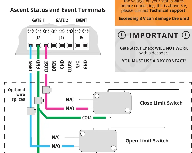
- The Status Terminals (J7, J13, J6) are designed for low voltage (3V or less).
- Check the voltage on your status wires before connecting. Exceeding 3V can damage the unit.
- Gate Status Check will not work with a decoder; you must use a dry contact.
Event Input:
- Used for accessories such as request-to-exit devices.
- Connect the device to the EVENT terminals (J6) as shown in the wiring diagram.
Wiegand Device Wiring
Caution: Disconnect power to the Ascent unit before connecting Wiegand devices to avoid damage.
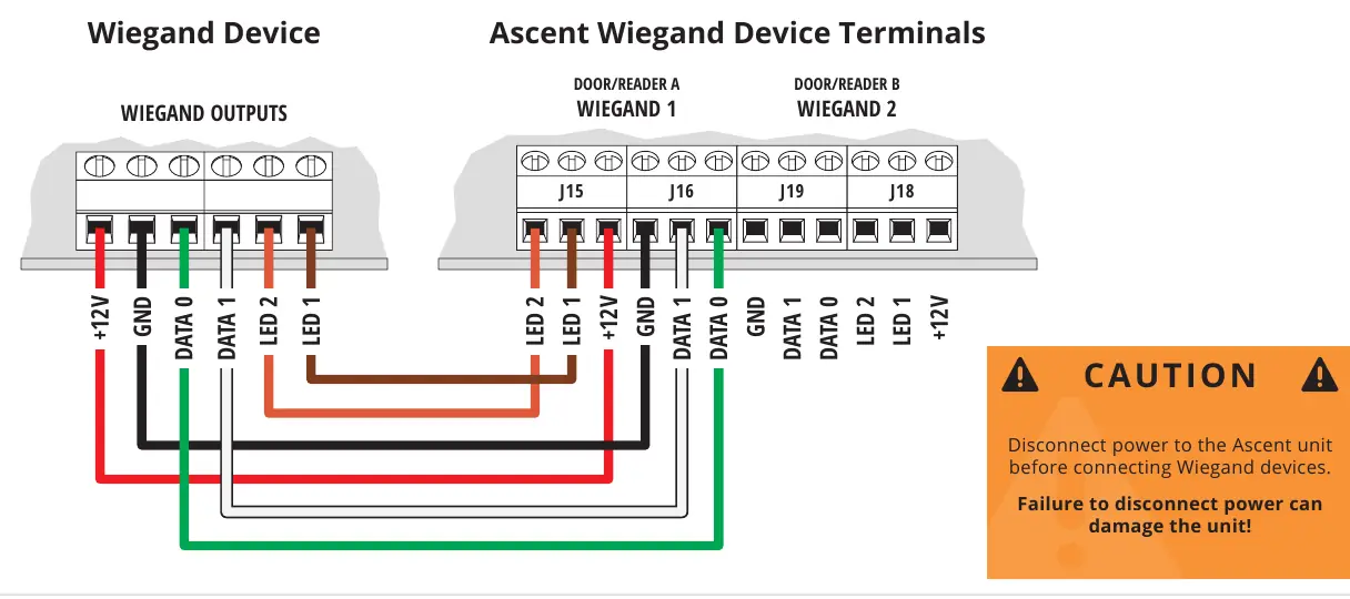
- Connect Wiegand devices (such as card readers) to the Wiegand Device Terminals (J15, J16, J19, J18).
- Ensure correct wiring of +12V, GND, LED, and Data lines as indicated on the terminal block labels.
Technical Specifications
- Input Voltage: 12-24 VAC/DC (no more than 10% beyond this range).
- Current Draw: Less than 600 mA @ 12 VDC; less than 320 mA @ 24 VDC.
- Compatibility: Not intended for solar applications.
Support
If you need help or have questions, please contact Summit Control at (972) 474-6422 or email [email protected]. Support is available Monday through Friday, 8am to 5pm Central.
Manufacturer information
Security Brands, Inc.
Practical help
Common problems
Unit has no signal
Ensure the hockey puck antenna is in place. If using alternate mounting, you must purchase and install the 4G LTE Antenna Extension Kit (Model 16-ANTX-1).
Unit will not work
The activation process must be complete. Follow the included Activation Guide to create an account.
Status check not working
Ensure you are using a dry contact. The unit will not work with a decoder.
Damage to unit during wiring
Do not exceed 24 VAC/DC power input. Ensure status wires are 3V or less. Disconnect power before wiring Wiegand devices.
Before use
- Verify power source is 12-24 VAC/DC.
- Ensure gate path is clear before operating.
- Complete the activation process via the Activation Guide.
- Check voltage on status wires (must be 3V or less).
- Disconnect power before connecting Wiegand devices.
- Seal all enclosure openings.
Specs in practice
- Current Draw (12VDC)
- Less than 600 mA.
- Current Draw (24VDC)
- Less than 320 mA.
- Status Terminals
- Max 3V; exceeding this voltage can damage the unit.
Images and diagrams
- Power/Relay Terminals: Shows connection for power source and gate operator.
- Status/Event Terminals: Shows wiring for limit switches and request-to-exit devices.
- Wiegand Terminals: Shows wiring for card readers or similar devices.
Model compatibility
- Not intended for solar applications.
- Requires Summit Control account for activation.
- Terminals vary widely across gate/door opener manufacturers.

Manual page author
Michael Turner
Technical manual editor
Reviews PDF manuals for structure, safety notes, and practical product details so readers can find the right information quickly.