Home / Security
Quick Start Guide for Security Brands Ascent M4 Entry System
Quick start guide for the Security Brands Ascent M4 cellular entry system. Includes mounting instructions, wiring diagrams for power, relays, status inputs, and Wiegand devices, plus activation and testing procedures.
Table of contents
Manual images
Click an image to enlargeQuick Start Guide
This document provides the essential steps to install and configure the Security Brands Ascent M4 cellular entry system. Please note that an uninterrupted cellular connection cannot be guaranteed, and an emergency egress or primary entry mechanism should always be used.
Unpacking and Mounting
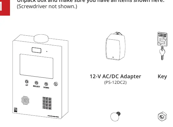
Before beginning, ensure you have all components: the Ascent unit, 12-V AC/DC adapter (PS-12DC2), four carriage bolts, four hex nuts, and the key. The screwdriver is not included.
- Unlock and open the front door of the unit to access mounting and wiring terminals.
- Mount the unit on a gooseneck pedestal using the included mounting hardware.
- Use all four carriage bolts when mounting.
- If using alternate mounting, the 4G LTE Antenna Extension Kit (Model 16-ANTX-1) must be purchased and installed to avoid signal loss.
- Seal all openings created in the enclosure to prevent damage.
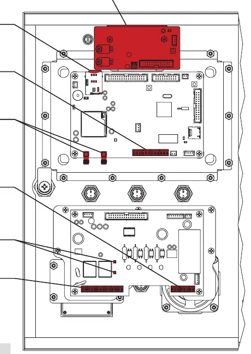
Wiring Connections
Feed wires through the back of the unit and connect them using the included screwdriver. Do not use excessive force.
- Power: Connect 12-24 VAC/DC power to the J3 terminal. Do not exceed 24 VAC/DC.
- Relays: Connect gate operator or door opener wires to Relay A (J4) or Relay B (J5) terminals.
- Third-Party Power: If not using the included adapter, ensure the power source is compatible (12-24 VAC/DC) and observe correct polarity.
Status and Event Inputs
The Ascent M4 features terminals for monitoring gate status and connecting request-to-exit devices.
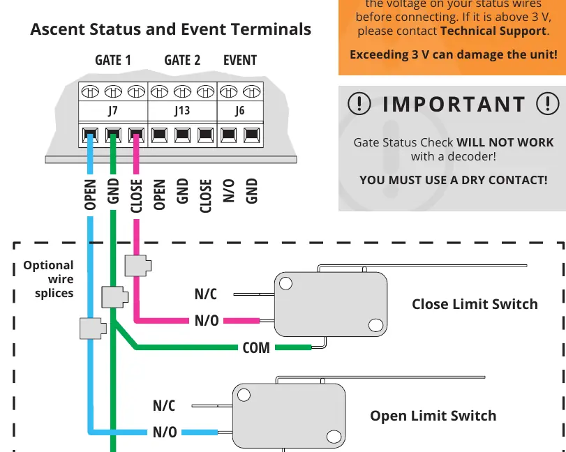
- Gate Status Check: Connect limit switches to the J7 (Gate 1) or J13 (Gate 2) terminals. Note: The status terminals are designed for low voltage (3 V or less). Do not use a decoder; you must use a dry contact.
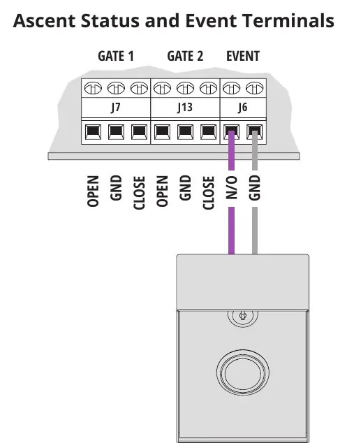
- Event Input: Connect request-to-exit devices to the J6 (Event) terminal.
Wiegand Device Connection
To connect Wiegand devices such as card readers:
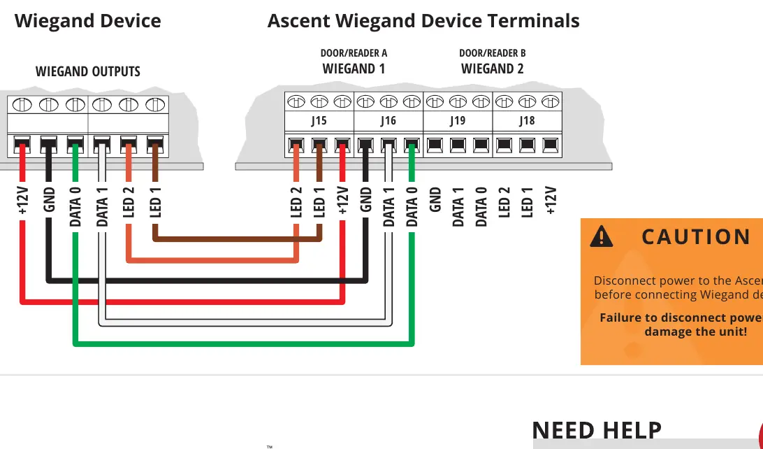
- Disconnect power to the Ascent unit before connecting Wiegand devices.
- Connect the device to the appropriate Wiegand terminals (J15, J16, J19, or J18) as shown in the wiring diagram.
System Activation and Testing
- Once wiring is complete, key in the temporary code 2012 on the keypad to confirm the gate opens.
- If the gate opens, close and lock the front door.
- The unit will not work until the activation process is complete. Follow the separate Activation Guide to create an account and begin using the system.
- Adding and deleting codes is managed through Summit Control, not the keypad.
Technical Specifications
- Input Voltage: 12-24 VAC/DC (no more than 10% beyond this range).
- Current Draw: Less than 690 mA @ 12 VDC; less than 420 mA @ 24 VDC.
- Compatibility: Not intended for solar applications.
Manufacturer information
Security Brands, Inc.
Practical help
Common problems
No signal
If using alternate mounting instead of a gooseneck pedestal, you must purchase and install the 4G LTE Antenna Extension Kit (Model 16-ANTX-1).
Unit not working
The unit will not function until the activation process is complete. Follow the included Activation Guide.
Gate Status Check not working
Ensure you are using a dry contact. The system will not work with a decoder.
Voltage damage
Do not exceed 24 VAC/DC for power or 3 V for status terminals. Check voltage before connecting.
Before use
- Unpack all items (Ascent unit, adapter, bolts, key).
- Ensure the gate path is clear before operating.
- Verify power source is 12-24 VAC/DC.
- Check voltage on status wires (must be 3V or less).
- Disconnect power before connecting Wiegand devices.
Specs in practice
- Input Voltage
- 12-24 VAC/DC (no more than 10% beyond this range).
- Current Draw
- Less than 690 mA @ 12 VDC or less than 420 mA @ 24 VDC.
- Status Terminals
- Designed for low voltage (3 V or less).
Images and diagrams
- Power and Relay Terminals: Connect power to J3, relays to J4/J5.
- Status and Event Terminals: Connect limit switches or request-to-exit devices to J7, J13, J6.
- Wiegand Terminals: Connect card readers to J15, J16, J19, J18.
Model compatibility
- Not intended for solar applications.
- Gate Status Check requires dry contact.
- Terminals vary widely across gate/door opener manufacturers.

Manual page author
David Miller
Documentation analyst
Organizes user manual content into clear summaries, with attention to model details, product context, and everyday usability.