Home / Air Quality Monitors
Installation Guide for Senva TotalSense Series Indoor Air Quality Sensor
Comprehensive installation and configuration guide for the Senva TotalSense Series Indoor Air Quality Sensor. Includes wiring diagrams, DIP switch settings, sensor calibration, and troubleshooting steps.
Table of contents
Manual images
Click an image to enlargeImportant Information
The Senva TotalSense series is an indoor air quality sensor designed for monitoring temperature, CO2, TVOC, particulate matter (PM), relative humidity (RH), CO, PIR occupancy, and ambient light. This device is not intended for life-safety applications. Installation should be performed by qualified trade installers only. Ensure the power supply is de-energized before installation or service.
Installation
Locate the device away from ventilation sources and heat-generating equipment. One sensor per 5000-7500 square feet is typically required. Mount the device at light switch height in a vertical orientation. Use insulating material behind the device to ensure reading accuracy. Do not install in multi-gang electrical boxes with line voltage or other electrical devices.
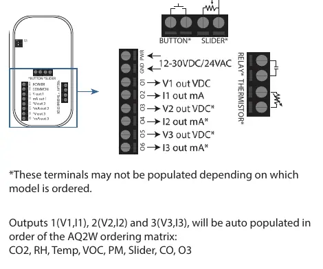
Wiring
Wire the device according to the specific application requirements. The device supports Analog, Communications (BACnet/Modbus), or combined wiring. Refer to the terminal diagrams on page 2 of the manual to identify the correct connections for your specific model configuration.
Setup and Configuration
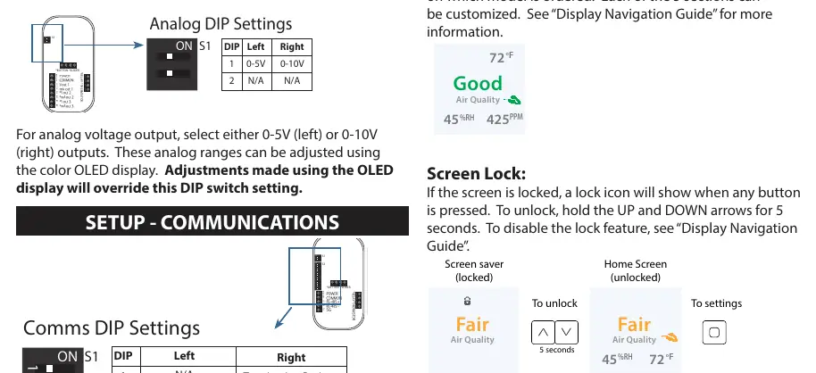
Analog Setup
Switch 1 is used for analog voltage output selection (0-5V or 0-10V). Adjustments made via the color OLED display will override the physical DIP switch settings.
Communications Setup
Use Switch 1 and Switch 3 to configure communication settings. Switch 1 sets the protocol (Modbus or BACnet) and termination resistance. Switch 3 is used to set the MAC address (0-127), baud rate, and data/parity/stop bits.
Display Navigation
Devices with an OLED display can be configured directly via the screen. Use the ENTER button to navigate menus and adjust parameters. If the screen is locked, hold the UP and DOWN arrows for 5 seconds to unlock.
Features
- Air Quality Monitoring: The device calculates average air quality based on sensor readings and displays an AQI rating.
- Setpoint Relay: Standard on most models (except PM). Thresholds can be adjusted via display or communications.
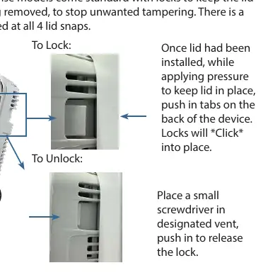
- Lid Locks: Located at all 4 lid snaps to prevent tampering. Push tabs on the back to lock; use a small screwdriver in the vent to release.
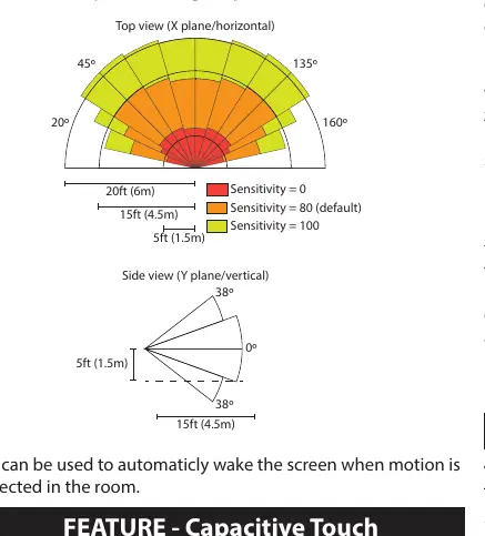
- PIR Occupancy: Triggers motion events based on adjustable sensitivity. Can be used to wake the screen.
- TVOC Operation: Includes an AI-based training mode that acclimates to the environment over 48 hours after reboot.
Calibration and Maintenance
The CO2 sensor features automatic baseline calibration. Field calibration is possible by comparing the sensor output to a calibration instrument and adjusting the offset in the display menu. For TVOC sensors, ensure exposure to fresh air at least once every 2 days to maintain accuracy.
Troubleshooting
If an alarm icon appears or the AQ ring blinks, the device has detected a sensor error. Navigate to Advanced Settings > Diagnostics to view details. For no output, verify wiring and power supply. For reading errors, ensure the unit is away from hot/cold sources and that the sensing element is inserted properly.
Technical Support
For further assistance, call toll-free at (866) 660-8864 or email [email protected].
Practical help
Common problems
Alarm icon on home screen or blinking AQ Ring
Device error detected. Navigate to Advanced Settings > Diagnostics to view specific error information.
No output
Check wiring connections and ensure the power supply meets the 16-30VDC/24VAC requirements.
Reading error
Verify control panel software configuration, check test instrument accuracy, ensure unit is away from hot/cold sources, and verify the sensing element is inserted properly.
Before use
- Ensure installation location is away from ventilation sources and heat-generating equipment.
- Mount at light switch height in a vertical orientation.
- Use insulating material behind the device for reading accuracy.
- Do not install in multi-gang electrical boxes with line voltage.
- De-energize power supply prior to installation or service.
Specs in practice
- Power Supply
- 16-30VDC/24VAC (3.5W nominal, 4W max without display; 4.3W nominal, 5W max with display).
Images and diagrams
- Wiring Diagrams: Shows terminal locations for Analog, Communications, and combined wiring configurations.
- DIP Switch Settings: Details how to configure analog voltage ranges, MAC addresses, and baud rates.
- PIR Coverage: Illustrates the detection range for the occupancy sensor.
Model compatibility
- PM sensor is not available on all models.
- Slider and pushbutton options are not available with the PM sensor.
- CO sensor is only available with the display option.

Manual page author
David Miller
Documentation analyst
Organizes user manual content into clear summaries, with attention to model details, product context, and everyday usability.