Industrial / Energy Monitoring
Installation and User Guide for Senva TG Series Toxic Gas Sensor
Comprehensive installation and operation guide for the Senva TG Series Toxic Gas Sensor. Includes wiring diagrams for BACnet/Modbus and Analog configurations, sensor maintenance schedules, and troubleshooting steps.
Table of contents
Manual images
Click an image to enlargeQuick Guide
The Senva TG Series Toxic Gas Sensor is designed to detect gas concentrations and communicate via BACnet/Modbus or Analog outputs. Key installation requirements include using wires rated for 75°C or above, de-energizing power before installation, and sealing conduits to prevent condensation and airflow interference. The device requires a warm-up time of up to 2 minutes after power is applied.
Installation
The sensor can be installed as a Wall Mount, Duct Mount, or Remote Mount unit.
- Wall Mount: Locate away from drafts. Mount 3-6 feet above the floor for most gases (CO, NO2, CO2, Oxygen, H2S). Mount Methane, Hydrogen, and Ammonia sensors within 1 foot of the ceiling. Propane sensors should be 1-3 feet above the floor. Refrigerant sensors should be 6 inches above the floor.
- Duct Mount: Drill a 3/4 inch hole in the duct. Install using the provided gasket and screws. The pickup tube ensures adequate airflow.
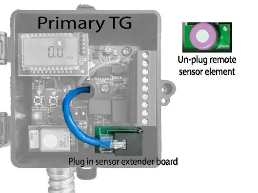
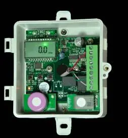
- Remote Mount: Use the TGx-REM kit for separate mounting heights. Replace the sensor board in the primary unit with the extender board, connect via the provided RJ45 cable, and plug the sensor board into the remote enclosure.
Wiring
Ensure all wiring complies with local electrical codes. Use a Class 2 LPS power supply or greater (15-30VDC or 24VAC).
- BACnet/Modbus: Communication wires can be daisy-chained. Use shielded twisted pair wire (14-26 AWG). Total wiring runs should not exceed 4000 feet. Use built-in EOL termination resistors if necessary.
- Analog: Connect to the appropriate inputs/outputs for 0-5V or 0-10V circuits.
- Relays: Fan and alarm relays are available for external control. Ensure fan relay set-points are uniform if multiple sensors are wired in parallel.
Operation
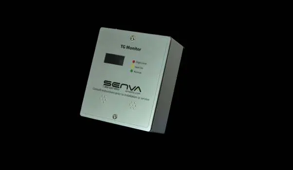
The device features an LCD display and LED indicators. Green indicates normal readings, Yellow indicates gas concentration above the fan set-point but below the alarm set-point, and Red indicates levels above the alarm set-point. The buzzer can be silenced by pressing all three buttons simultaneously.
Maintenance
Periodic maintenance is required to ensure accuracy.
- Every 6 Months: Retest and recalibrate H2S, Ammonia, and Refrigerant sensors using NIST traceable reference gas. Visually inspect for damage and clean exterior intake ports.
- Annual: Conduct a bump test for Methane, Propane, and Hydrogen. Retest and recalibrate Oxygen, CO, and NO2 sensors.
- Sensor Replacement: Power down the unit, remove the old element, plug in the new element, and re-apply power.
Troubleshooting
If the device is not functioning correctly, check the following:
- No output: Verify wiring and power supply requirements.
- Sensor reading error: The sensor may be contaminated or at the end of its life; replace the sensor element.
- Relay function issues: Verify set-points and test gas concentration. Ensure there are no drafts during testing.
- Chirping noise: Indicates a faulty or missing sensor; replace the sensor element.
- Refrigerant sensor unstable: Requires 1-3 hours of runtime post-installation to stabilize.
Practical help
Common problems
No output
Check wiring and ensure the power supply meets the 15-30VDC/24VAC requirements.
Sensor reading error
The sensor is likely contaminated or at the end of its service life. Replace the sensor element.
Chirping noise
The reliability feature has detected a faulty or missing sensor. Replace the sensor element.
Refrigerant sensor unstable at installation
Allow 1-3 hours of runtime post-installation for the sensor value to stabilize.
Before use
- De-energize power supply prior to installation.
- Use installation wires rated for 75°C and above.
- Seal both top and bottom of the conduit to prevent condensation.
- Verify mounting height based on the specific gas type (e.g., 0.5-1ft from ceiling for Methane/Hydrogen/Ammonia).
- Ensure sensor is accessible for maintenance.
Specs in practice
- Power Supply
- 15-30VDC or 24VAC, 50/60Hz, 4W max.
- Relay Rating
- 1A @ 24VAC/30VDC (No Mains Connection).
Images and diagrams
- Wiring diagrams are provided for both BACnet/Modbus and Analog configurations.
- Remote mounting instructions detail the use of the sensor extender board and RJ45 cable.
Model compatibility
- Compatible with BACnet MS/TP and Modbus RTU/ASCII networks.
- Analog outputs support 0-10V, 0-5V, 1-5V, and 4-20mA.

Manual page author
Michael Turner
Technical manual editor
Reviews PDF manuals for structure, safety notes, and practical product details so readers can find the right information quickly.