Home / Air Quality Monitors
User Manual for Senva TotalSense Series
Quick guide for navigating and configuring the Senva TotalSense Series air quality sensor. Learn how to adjust display settings, analog outputs, air quality thresholds, relay configurations, and interpret diagnostic codes.
Table of contents
Manual images
Click an image to enlargeQuick Guide
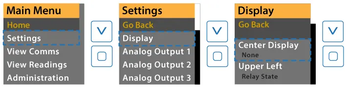
The Senva TotalSense Series air quality sensor features an OLED display for monitoring and configuration. If the screen is locked (indicated by a lock icon), hold the up and down arrows for 5 seconds to unlock. Use the 'enter' button to access the setup menu and navigate through parameters.

Display Navigation and Settings
The display can be customized to show various sensor readings in different corners. To change settings, press 'enter' to access the setup menu, navigate to 'Display', and select the desired corner (Center, Upper Left, Upper Right, Lower Left, Lower Right) to assign a value such as Temp, RH, CO2, TVOC, PM, or Air Quality.
Additional display settings include:
- Screen Lock: Enable or disable screen lock mode (initiates after 60s of inactivity).
- Screen Saver: Choose what to display when inactive or turn the display off.
- Brightness: Adjust brightness for the home screen and screen saver.
- SS Timeout: Set the time before the screen saver activates (1-120 minutes).
Analog Output Configuration
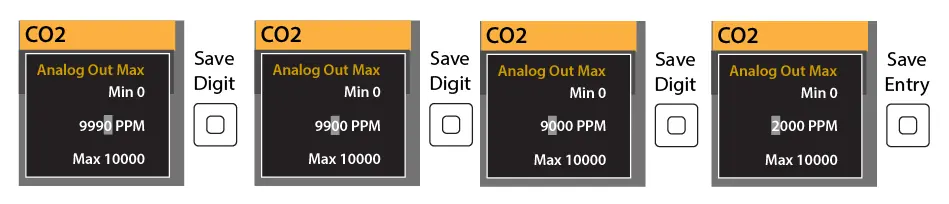
Analog outputs can be configured to output specific sensor readings. Settings include:
- Source: Select the sensor reading to output (e.g., CO2, RH, Temp, TVOC).
- Min/Max Voltage/Current: Define the analog scale (e.g., 0-10V, 4-20mA).
- PID Settings: Configure PID control loop parameters (Proportional, Integral, Derivative coefficients) and PID Invert. Note that PID output controls are only available on Analog output 1 or Analog output 3 for comms+analog devices.
Air Quality and Source Settings
The device allows for detailed configuration of air quality thresholds and individual sensor parameters:
- Air Quality Thresholds: Adjust 'Good-Fair' and 'Fair-Poor' thresholds to define air quality ratings.
- Sensor Enable: Enable or disable specific sensors (Temp, RH, CO2, PM, VOC, CO, Ozone) used in the air quality calculation.
- Source Parameters: Each sensor type (CO2, PM, RH, Temp, TVOC, CO, Ozone, Ambient Light) has specific settings for calibration, offsets, and analog scaling.
Relay and PIR Settings
The relay can be configured to activate based on specific sensor readings:
- Source: Choose the measurement that activates the relay (e.g., CO2, RH, Temp, PIR).
- Thresholds: Set 'Turn On' and 'Turn Off' thresholds based on the sensor's full-scale range.
- Polarity: Select N.O. (Normally Open) or N.C. (Normally Closed) operation.
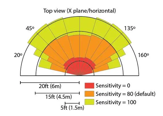
- PIR Sensitivity: Adjust motion sensor sensitivity (0-100) and occupied delay time.
Diagnostics and Troubleshooting
The device provides diagnostic status codes in binary format to help identify issues. If a status code appears, consult the diagnostic tables in the manual. Common statuses include EEPROM faults, sensor data errors, or sensor not ready states. For most hardware faults, contact the factory.
Practical help
Common problems
Screen is locked
Hold the up and down arrows for 5 seconds to unlock the display.
Sensor not ready
Check the diagnostic status. Some sensors require a warm-up period (e.g., 4 minutes for TVOC) or training mode.
Relay not activating
Verify the 'Relay Settings > Source' is correctly set and the 'Turn On' threshold is appropriate for the selected sensor range.
Before use
- Ensure the device is connected and powered.
- Verify the sensor is installed correctly.
- Unlock the screen if a lock icon appears.
Specs in practice
- ABC (Automatic Baseline Calibration)
- Automatically calibrates the CO2 sensor to expected unoccupied levels.
- N.O./N.C. Relay
- Normally Open (N.O.) closes when activated; Normally Closed (N.C.) opens when activated.
Images and diagrams
- PIR Sensitivity diagram shows the detection range and angle for different sensitivity settings.
- Menu navigation diagrams illustrate how to access settings and adjust numerical values.
Model compatibility
- PID output controls are only available on Analog output 1 or Analog output 3 for comms+analog devices.

Manual page author
Emily Carter
User documentation editor
Prepares concise manual descriptions and highlights the most useful setup, operation, and maintenance information for readers.