Smart Home / Smart Plugs & Strips
Shelly 1 Gen3 Smart Relay Switch
Quick guide for the Shelly 1 Gen3 smart relay switch. Learn how to install, wire for different voltages (110-240V AC, 24-48V DC, 12V DC), and configure your device for smart home automation.
Table of contents
Manual images
Click an image to enlargeImportant information from the manual
The Shelly 1 Gen3 is a smart relay switch designed for home automation. It supports multiple power supply options: 110-240V AC, 24-48V DC, and 12V DC. Installation must be performed by a qualified electrician. Always disconnect the power supply before performing any installation or wiring work.
Installation and Wiring
The device supports three distinct wiring configurations depending on your power source. Ensure you use the correct diagram for your specific voltage.
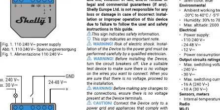
110-240V AC Wiring
- Connect the Line wire to the L terminal.
- Connect the Neutral wire to the N terminal.
- Connect the Load to the O terminal.
- Connect the Input to the I terminal.
- Connect the Switch to the SW terminal.
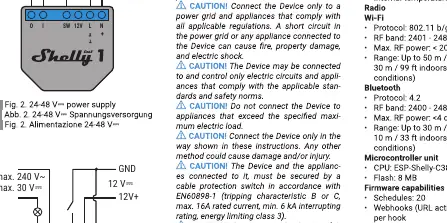
24-48V DC Wiring
- Connect the positive wire to the + terminal.
- Connect the ground wire to the GND terminal.
- Connect the Load to the O terminal.
- Connect the Input to the I terminal.
- Connect the Switch to the SW terminal.
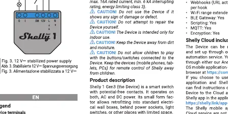
12V DC Wiring
- Connect the positive wire to the + terminal.
- Connect the ground wire to the GND terminal.
- Connect the Load to the O terminal.
- Connect the Input to the I terminal.
- Connect the Switch to the SW terminal.
Initial Setup
Once installed, the device can be configured via the Shelly Cloud app or a web interface. To set up the device:
- Power on the device.
- The device will create its own Wi-Fi access point.
- Connect your smartphone or computer to the Shelly Wi-Fi network.
- Open a web browser and navigate to 192.168.33.1 to access the web interface for configuration.
- Follow the on-screen instructions to connect the device to your local Wi-Fi network.
Safety and Maintenance
- Do not install the device in a location where it can get wet.
- Use only solid core wires or stranded wires with ferrules.
- Ensure the device is not exposed to excessive heat or moisture.
- If the device is damaged, do not attempt to repair it yourself.
Specifications
- Power supply: 110-240V AC, 24-48V DC, or 12V DC.
- Connectivity: Wi-Fi 802.11 b/g/n, Bluetooth.
- Operating temperature: -20°C to 40°C.
- Max altitude: 2000m.
Practical help
Common problems
Device not connecting to Wi-Fi
Ensure the device is in Access Point (AP) mode (LED flashing). If not, press and hold the button for 10 seconds to reset.
Device not responding
Verify that the power supply matches the wiring diagram used (110-240V AC, 24-48V DC, or 12V DC).
Before use
- Turn off the main power supply before installation.
- Verify your power source voltage (110-240V AC, 24-48V DC, or 12V DC).
- Ensure you have solid core wires or stranded wires with ferrules.
- Check that the Wi-Fi signal is available at the installation location.
Specs in practice
- 24-48V DC / 12V DC
- Low voltage DC power supply inputs for specific applications.
Images and diagrams
- The diagrams illustrate the correct terminal connections for L (Line), N (Neutral), O (Output), I (Input), SW (Switch), +, and GND.
- Ensure the wiring matches the specific voltage diagram provided for your power source.
Model compatibility
- Supports 110-240V AC, 24-48V DC, and 12V DC power supplies.
- Requires Wi-Fi 802.11 b/g/n for smart features.

Manual page author
David Miller
Documentation analyst
Organizes user manual content into clear summaries, with attention to model details, product context, and everyday usability.