Lighting / Controllers & Dimmers
User Guide for Shelly Wave Plug UK
A comprehensive user guide for the Shelly Wave Plug UK. This manual covers installation, Z-Wave network inclusion and exclusion, factory reset procedures, LED status indicators, and configuration parameters for power measurement and alarm...
Table of contents
Manual images
Click an image to enlargeQuick Guide from the Manual
The Shelly Wave Plug UK is a smart plug designed for remote control of electrical appliances and power consumption measurement. It operates on the Z-Wave wireless protocol. Before installation, ensure the device is not damaged and that the appliance load does not exceed the maximum rating. The device is intended for indoor use only.
About the Device
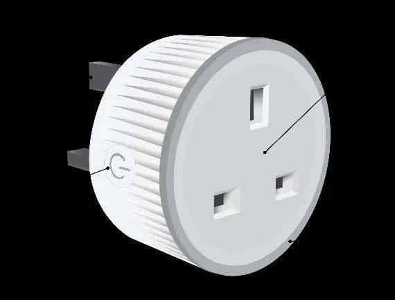
The device features a plug (A), an S button (B) for manual control and Z-Wave operations, a socket (C) for the appliance, and an LED indicator (D) for status and alarms.
Installation
Plug the device into a standard BS 1363 (Type-G) wall socket. Once connected, you can plug your appliance into the device socket. To power the appliance on, press the S button briefly.
Z-Wave Network Inclusion and Exclusion
Inclusion (Adding to network):
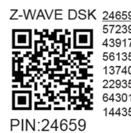
- SmartStart: Scan the QR code on the device label with your gateway. Connect the device to power; it will be added automatically within 10 minutes.
- Manual Inclusion: Connect the device to power. Ensure the blue LED is blinking (Mode 1). Enable inclusion mode on your gateway. Press and hold the S button until the LED turns solid blue, then release and hold again (>2s) until the blue LED blinks in Mode 3. The device will enter Learn mode.
Exclusion (Removing from network):
- Connect the device to power. Ensure the green LED is blinking (Mode 1). Enable exclusion mode on your gateway. Follow the same S button procedure as for inclusion.
Factory Reset
To reset the device to factory defaults, press and hold the S button until the LED turns solid blue. Press the S button multiple times until the LED turns solid red. Press and hold (>2s) until the red LED blinks in Mode 3. The device will reset and be removed from the network.
LED Signalization
The LED provides visual feedback on the device status:
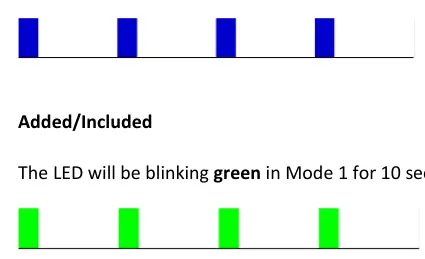
- Blinking Blue (Mode 1): Device is not included in a network.
- Blinking Green (Mode 1): Device is included in a network.
- Solid Green: Relay ON, load is 0W.
- Solid Yellow: Relay ON, load is >0W and up to 85% of max power.
- Solid Red: Relay ON, load is >85% of max power.
- Blinking Red (Mode 4): Alarm mode (Overcurrent, Overheat, Overvoltage, or Power supply fault).
Alarm Modes
The device includes protection against Overheat, Overcurrent, and Overvoltage. When an alarm is triggered, the device switches off the output. To reset the alarm, perform a power cycle, remote reboot (Parameter 117), or press the S button.
Configuration Parameters
The device supports various Z-Wave parameters for customization, including:
- Parameter 17: Restore state after power failure (0: Save last state, 1: Remain OFF).
- Parameter 19/20: Auto OFF/ON timer settings.
- Parameter 23: Contact type (NO/NC).
- Parameter 36: Power report threshold (percentage).
- Parameter 91-94: Alarm responses (Water, Smoke, CO, Heat).
- Parameter 117: Remote device reboot.
- Parameter 120: Factory reset.
Technical Specifications
- Power supply: 230 V ±10 %, 50/60 Hz
- Max switching current: 13 A
- Max switching voltage: 260 V AC
- Power consumption:< 0.7W
- Operating temperature: -20°C to 40°C
- Z-Wave frequency: 868.4 MHz
Practical help
Common problems
Device not added to Z-Wave network
Check if the blue LED is blinking in Mode 1. If so, it is not added. Ensure the gateway is in inclusion mode and try the S button inclusion procedure.
Device output switched off unexpectedly
Check for alarm conditions (Overheat, Overcurrent, Overvoltage). The LED will blink red in Mode 4. Reset by power cycle, remote reboot, or pressing the S button.
Device not responding to commands
Ensure the device is powered. If it is unresponsive, use Parameter 117 to perform a remote reboot via your gateway.
Before use
- Verify the wall socket is a standard BS 1363 (Type-G) type.
- Ensure the appliance load does not exceed 13A.
- Keep the device away from moisture and damp environments.
- Locate the DSK PIN code on the device label for S2 security inclusion.
- Ensure your Z-Wave gateway is ready for inclusion.
Specs in practice
- Max switching current
- 13 A - The maximum electrical current the plug can handle.
- Power measurement
- Yes - The device monitors and reports power consumption in Watts and kWh.
- Z-Wave frequency
- 868.4 MHz - The radio frequency used for communication.
- Operating temperature
- -20°C to 40°C - The ambient temperature range for safe operation.
Images and diagrams
- A: Plug - Connects the device to the wall socket.
- B: S button - Used for inclusion, exclusion, factory reset, and manual control.
- C: Socket - Where the electrical appliance is plugged in.
- D: LED indicator - Displays device status, network inclusion, and alarm states.
Model compatibility
- Requires a Z-Wave gateway for smart features.
- Compatible with BS 1363 (Type-G) sockets and plugs.
- Supports Security 2 (S2) authentication for secure network inclusion.

Manual page author
Emily Carter
User documentation editor
Prepares concise manual descriptions and highlights the most useful setup, operation, and maintenance information for readers.