Industrial / Communication Modules
User Manual for Siemens SIMATIC ET 200SP CM PtP Communication Module
Comprehensive user guide for the Siemens SIMATIC ET 200SP CM PtP communication module (6ES7137-6AA00-0BA0). Includes installation, wiring diagrams, interface configuration, programming instructions, and diagnostic LED meanings.
Quick answers from the manual
Quick answer
- The CM PtP communication module (6ES7137-6AA00-0BA0) enables point-to-point data exchange between programmable controllers and external devices via RS232 or RS422/485 interfaces. p. 9, 11
Key actions
- Wire the module using the appropriate BaseUnit pin assignment for RS232 or RS422/485. p. 17, 18
First start
- Configure the module using STEP 7 (TIA Portal) or GSD file integration. p. 12, 19
Problems and fixes
DIAG LED flashes
Module is in startup or parameters not assigned.
p. 24
PWR LED off
Check the voltage supply of the load group.
p. 24Technical specifications
| Parameter | Value | Meaning | Pages |
|---|---|---|---|
| Supply voltage | 24 V DC | Operating voltage range 19.2 V to 28.8 V | p. 25 |
Where to find it in the PDF
- Product Overview p. 9, 10, 11, 12
- Connecting p. 17, 18
- Technical Specifications p. 25, 26, 27, 28
Table of contents
Manual images
Click an image to enlargeQuick guide from the manual
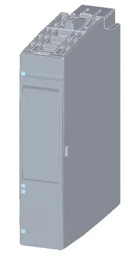
The Siemens SIMATIC ET 200SP CM PtP communication module (6ES7137-6AA00-0BA0) is designed for point-to-point data exchange between programmable controllers and external devices. This manual covers the installation, wiring, configuration, and diagnostics required for operation.
Product overview
The module supports RS232 and RS422/485 interfaces, allowing for flexible communication with various devices. It is short-circuit proof and electrically disconnected. Key supported protocols include Freeport, 3964(R), Modbus master/slave (RTU), and USS.
Connecting
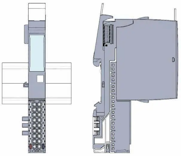
The module connects via a BaseUnit. Ensure the power supply is disconnected before wiring. The module supports two main interface types:
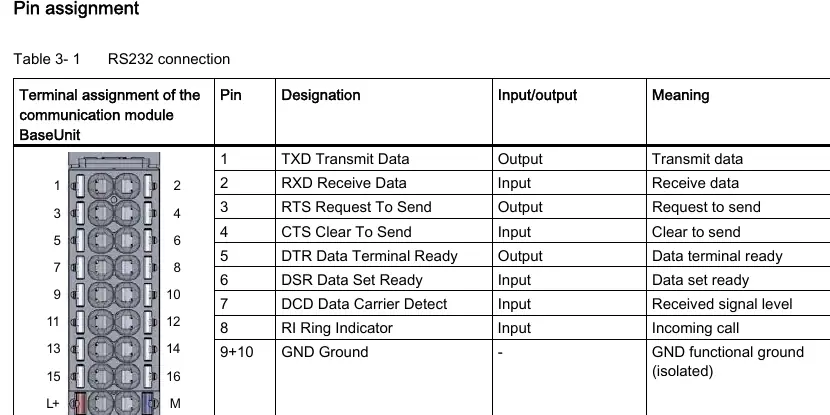
- RS232 interface: Used for serial data transmission with signals including TXD, RXD, RTS, CTS, DTR, DSR, RI, and DCD.
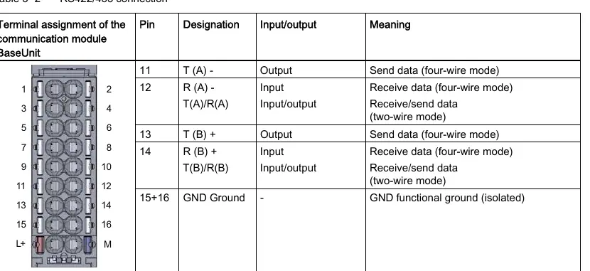
- RS422/485 interface: A differential voltage interface for serial data transmission.
Always ensure the cable shield is installed on a grounding rail to maintain EMC values.
Programming
Communication is managed via special instructions in STEP 7 (TIA Portal). Key instructions include:
- Port_Config: Dynamically assign basic interface parameters.
- Send_P2P / Receive_P2P: Send and receive data to/from a communication partner.
- Modbus_Master / Modbus_Slave: Configure the port for Modbus RTU communication.
Diagnostics
The module features LED displays for status monitoring:
- DIAG: Indicates module status (On = configured/ready, Flashing = startup/not assigned, Flashing = error).
- TX / RX: Indicates data transmission/reception.
- PWR: Indicates power supply status.
Technical specifications
The module operates on 24 V DC (19.2 V to 28.8 V). It has a current consumption of 29 mA and a power loss of 0.7 W. The operating temperature range is 0 °C to 60 °C for horizontal installation and 0 °C to 50 °C for vertical installation.
Manufacturer information
Siemens AG
Practical help
Common problems
DIAG LED flashing
The module is in startup mode or parameters have not been assigned yet.
PWR LED off
Check the voltage supply of the load group.
Interface not transmitting/receiving
Verify wiring and ensure the interface configuration (RS232/RS422/485) matches the connected device.
Before use
- Ensure the power supply is disconnected before wiring the communication module.
- Verify the BaseUnit is correctly installed.
- Check the interface type (RS232 or RS422/485) required for your application.
- Ensure STEP 7 (TIA Portal) is installed for configuration.
- Confirm the cable shield is connected to a grounding rail.
Specs in practice
- Supply voltage
- 24 V DC (19.2 V to 28.8 V).
- Max. cable length (RS232)
- 15 meters.
- Max. cable length (RS422/485)
- 1200 meters.
- Data transmission rate
- 300 to 115200 bps.
Images and diagrams
- Pin assignment tables for RS232 and RS422/485 connections.
- LED display locations for diagnostics.
- Dimensional drawing for cabinet installation.
Model compatibility
- Compatible with SIMATIC S7-300, S7-400, S7-1500, and standard Profinet Controllers.
- Not compatible with SIMATIC S7-1200.

Manual page author
Michael Turner
Technical manual editor
Reviews PDF manuals for structure, safety notes, and practical product details so readers can find the right information quickly.