Home / Electrical Accessories
Installation Instructions for Sigma Widespread Lavatory Set
Step-by-step installation guide for the Sigma Widespread Lavatory Set. Includes instructions for spout, supply valve, and drain assembly, plus handle measurement charts and maintenance cautions.
Table of contents
Manual images
Click an image to enlargeQuick guide from the manual
This document provides installation instructions for the Sigma Widespread Lavatory Set. It is intended for use by a qualified or licensed plumber. Before beginning, inspect all pre-assembled parts. The installation requires 1-1/4 inch holes in the deck for both the spout and the supply valves. Always flush all lines of debris before final connection and check the system for leaks before closing the deck.
Spout Installation
The spout assembly requires careful attention to the tee fitting to ensure a proper seal.
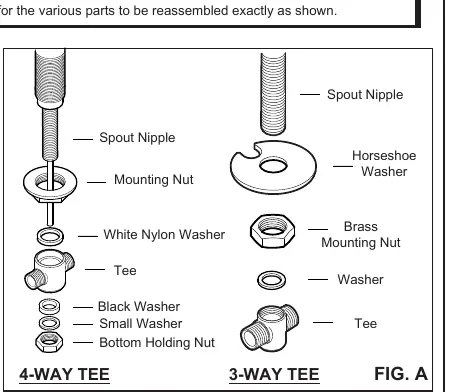
- Prepare a 1-1/4 inch hole in the deck.
- Remove the tee, mounting nut, and horseshoe washer (for 3-way tees).
- Drop the spout through the top of the deck and secure it from underneath using the mounting nut.
- Reassemble the tee assembly. Ensure the Bottom Holding Nut is snugly tightened to complete the seal.
Supply Valve Installation
The valves are shipped pre-assembled with handles. Remove the handle pieces and the top locking nut before installation.
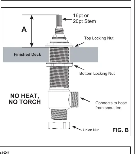
- Install hot and cold valves from underneath the deck using the locking nuts.
- Adjust the valve height so that Measurement A matches the chart provided in the manual. Measurement A varies based on the handle selection.
- Valve bodies are marked with stickers to distinguish hot (red) from cold (blue).
- Test the height by temporarily placing the handle pieces over the valve. Once the fit is correct, remove the handles and tighten the locking nuts with a wrench.
- Remount the handle pieces. The handle should open and close in a 1/4 turn.
- Connect the stainless steel braided hoses from the tee to the outlets of the supply valves. Hand-tighten the hoses; do not use grippers or excessive force, as this will break the seal.
Handle Measurement Chart
The installation height (Measurement A) depends on the specific handle group. Refer to the chart in the manual to identify your handle group (Group 1 through Group 9) and the corresponding measurement in inches.
Drain Installation
The manual covers two types of drain assemblies:
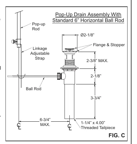
- Pop-up Drain (FIG C): Requires applying neutral sealant to the bottom of the flange. Ensure the hole for the ball rod faces the back of the sink. Connect the pop-up rod to the linkage adjustable strap and secure with the screw.
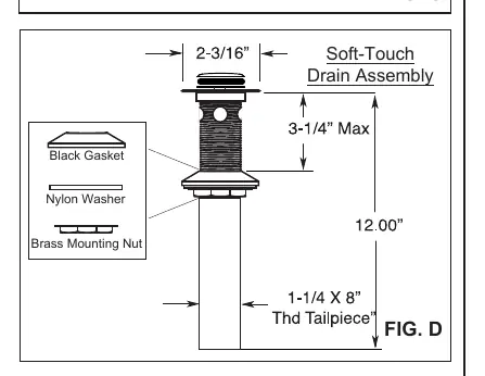
- Soft-touch Drain (FIG D): Requires applying neutral sealant to the bottom of the flange and securing the body against the sink with the provided washers and mounting nut.
Important Cautions and Maintenance
- Sealants: Do not use lead-based or acidic curing sealants, as these will void the finish warranty. Use only neutral curing sealants.
- Cartridge Care: Do not force the handle to close the valve. If debris clogs the cartridge, flush it carefully without disassembling.
- Lead Warning: This faucet contains lead. Always run the water for a few seconds before use for drinking or cooking. Use only cold water for drinking or cooking.
- No Heat: Do not use heat or torches near the installation.
Practical help
Common problems
Spout leaks after installation
Ensure the tee assembly is correctly reassembled and the Bottom Holding Nut is snugly tightened.
Handle does not close the valve properly
Do not force the handle. Flush the cartridge to remove debris without disassembling it.
Finish warranty voided
Avoid using lead-based or acidic curing sealants, silicone, mastic, or plumber's putty. Use only neutral curing sealants.
Before use
- Ensure you have 1-1/4 inch holes in the deck.
- Inspect all pre-assembled parts before starting.
- Identify your handle group to determine the correct Measurement A.
- Flush all plumbing lines of debris before final connection.
- Check the system for leaks before closing the deck.
Specs in practice
- Measurement A
- The required valve height from the deck surface, determined by the specific handle model.
Images and diagrams
- FIG A: Exploded view of the spout and tee assembly components.
- FIG B: Valve installation details and Measurement A reference.
- FIG C: Components and assembly steps for the Pop-up Drain.
- FIG D: Components and assembly steps for the Soft-touch Drain.
Model compatibility
- Requires 1-1/4 inch holes in the deck.
- For residential use only.
- Not suitable for in-the-wall installations without access.

Manual page author
David Miller
Documentation analyst
Organizes user manual content into clear summaries, with attention to model details, product context, and everyday usability.