Industrial / Control Panels
Installation and Operation Manual for SJE Rhombus 1022888E-IFS3 Control Panel
Comprehensive installation and operation guide for the SJE Rhombus 1022888E-IFS3 control panel. Includes detailed instructions for mounting, float switch configuration, timer programming, pump sequence settings, and troubleshooting...
Table of contents
Manual images
Click an image to enlargeQuick guide from the manual
The SJE Rhombus IFS (Installer Friendly Series) control panel is designed to monitor and control pump systems. This manual covers installation, float switch setup, timer programming, and troubleshooting. Important: Installation and servicing must be performed by a licensed electrician in accordance with NFPA-70 and local codes. Ensure all conduit entries are sealed to prevent moisture or gas ingress.
Installation
The control panel must be mounted in a location not subject to submersion. Follow these steps for installation:
- Determine the mounting location. If the distance exceeds float or pump cable lengths, use an SJE Rhombus liquid-tight junction box.
- Mount the control panel using the furnished devices.
- Determine conduit entrance locations. Float cables must run in a separate conduit from power and pump cables.
- Drill holes for connectors and attach them securely.
- If using a junction box, mount it to a proper support (do not mount inside the sump or basin).
- Identify and label wires before pulling through conduit.
- Connect pump, control, and alarm incoming power conductors to the proper terminals as shown on the schematic.
Installation of Floats
Proper float installation is critical for system function. Ensure floats have free range of motion without touching each other or other equipment.
- Determine the normal operating level and desired float configuration (see Figures 2-5).
- Mount float switches at appropriate levels.
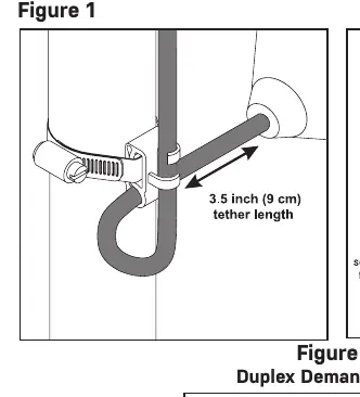
- For clamp installation: Place the cord into the clamp, locate at the desired activation level, and secure to the discharge pipe. Tighten the hose clamp with a screwdriver, but do not overtighten to avoid damaging the plastic clamp.
- Ensure the float cable does not touch the excess hose clamp band.
Operations
The panel features several modes of operation:
- Hand Operation: Press and hold the HAND button to override the stop/redundant float. The pump runs until the button is released.
- Off Operation: The panel is in the OFF mode.
- Auto Operation: In timed dose mode, the timer controls pump ON/OFF time. In demand mode, stop and start floats control the pump.
- Indicators: Green control and alarm power indicators are mounted on the interior circuit board.
Programming
Program Timer On & Off Times:
- Press and hold the SET button for 3 seconds until 'Prog' is displayed.
- The display will flash 'On', then the time in hh:mm:ss.
- Follow Section A: Press SET to display time, NEXT to select digits, UP to change time, and SET to save.
- Repeat for OFF times.
Program Pump Sequence (Duplex only):
- Press and hold SET for 3 seconds until 'Prog' is displayed.
- Press NEXT until 'ALtErn' flashes with 'ALt', '2-1', or '1-2'.
- Press SET to display the sequence, then UP to change.
- Press and hold SET for 3 seconds to save.
Troubleshooting
If the system is not functioning correctly:
- Float Controls: Check floats during their entire range of operation. Measure float resistance with an ohmmeter (R X 1 scale). Infinity indicates a blown float; near zero indicates a closed float.
- Fuse: Check continuity with an ohmmeter. Replace with a fuse of the same type, voltage, and amp rating.
- Alarm Light/Horn: Use the test/normal/silence switch in the 'test' position. If the light or horn does not activate, replace with the same type.
Practical help
Common problems
Pump system not functioning properly
Verify control switch cables are wired and mounted in the correct order. Ensure floats have free range of motion.
Blown fuse
Check continuity with an ohmmeter on R X 1 scale. Replace with a fuse of the same type, voltage, and amp rating.
Alarm light or horn not working
Hold the test/normal/silence switch in the 'test' position. If it does not activate, replace the component.
Before use
- Ensure installation is performed by a licensed electrician.
- Verify power supply voltage, amperage, and phase meet pump requirements.
- Seal all conduit entries to prevent moisture or gas ingress.
- Ensure float cables run in separate conduit from power and pump cables.
- Verify correct operation after installation is complete.
Specs in practice
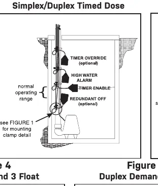
- Timed Dose (t-dose)
- Timer controls pump ON and OFF time as long as the low level float is raised.
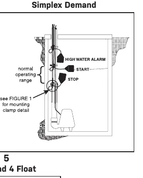
- Demand Dose (d-dose)
- Stop and start floats control the pump operation.
Images and diagrams
- Figure 1: Proper float mounting clamp installation on discharge pipe.
- Figure 2: Simplex/Duplex Timed Dose float configuration.
- Figure 3: Simplex Demand float configuration.
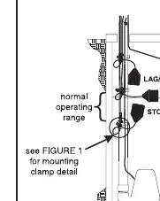
- Figure 4: Duplex Demand 3 Float configuration.
- Figure 5: Duplex Demand 4 Float configuration.
Model compatibility
- Do not mount the junction box inside the sump or basin.
- Float cables require separate conduit from power and pump cables.
- Changing dip switch positions will change the operation of the panel.

Manual page author
Emily Carter
User documentation editor
Prepares concise manual descriptions and highlights the most useful setup, operation, and maintenance information for readers.