Industrial / Control Panels
Installation and Operation Manual for SJE Rhombus 1010434G-TD Timed Dosing Control
Comprehensive installation and operation guide for the SJE Rhombus 1010434G-TD Timed Dosing Control. Includes detailed instructions for float switch configuration, timer settings, wiring diagrams, and troubleshooting procedures.
Table of contents
Manual images
Click an image to enlargeQuick Guide from the Manual
The SJE Rhombus Type TD Timed Dosing Control is designed for use with two, three, or four float systems. This panel must be installed and serviced by a licensed electrician in accordance with the National Electric Code NFPA-70 and local electrical codes. All conduit entries must be sealed to prevent moisture or gases from entering the panel. The NEMA 4X enclosure is suitable for indoor or outdoor use.
Installation of Floats
Correct float configuration is critical for proper pump system function. Ensure all power is turned off before installation.
- Use the float label kit to identify cables on both the float and the stripped ends.
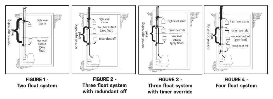
- Determine the operating level and desired configuration (see Figures 1-4).
- Mount float switches at appropriate levels, ensuring they have a free range of motion without touching each other or other equipment.
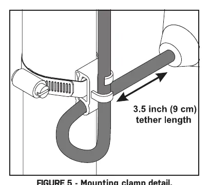
- For mounting clamp installation: place the cord into the clamp, locate it at the desired activation level, and secure it to the discharge pipe. Tighten the hose clamp with a screwdriver, but do not overtighten to avoid damaging the plastic clamp.
- If using an optional redundant off float, mount it slightly below the low level cutout float but above the pump.
- If using an optional timer override float, position it at the required level in the basin.
Mounting the Control Panel
Determine the mounting location. If the distance exceeds the length of the float switch or pump power cables, splicing is required. For outdoor or wet installations, use an SJE Rhombus liquid-tight junction box.
- Mount the control panel using the furnished devices.
- Drill proper size holes for the type of connectors being used.
- Attach cable/conduit connectors to the control panel.
- If using a junction box, mount it to a proper support (do not mount inside the sump/basin).
- Identify and label each wire before pulling through conduit.
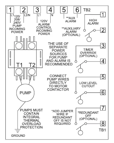
- Connect pump wires and float switch cables to the proper terminals. If the redundant off float is not required, place a jumper wire across TB1-7 and TB1-8.
- Connect incoming power conductors to the proper terminals.
Setting the Timer
The timer controls the pump "on" and "off" cycles. To adjust:
- Remove the timer by clipping the tie strap and pulling it out of the socket.
- Adjust the OFF time range selector and the OFF dial to the desired period.
- Adjust the ON time range selector and the ON dial to the desired period.
- Place the timer back in the socket.
- Note: The "OFF" time is cycled first.
Operations and Troubleshooting
Float Controls: Check floats during their entire range of operation. Measure float resistance to determine if they are operating properly. In the "off" position, the ohmmeter should read infinity (high resistance). In the "on" position, it should read close to zero.
Magnetic Contactor Coil: Disconnect one coil lead and measure resistance on the R X 1 scale. A defective coil will read zero (short) or infinity (open).
Fuses: Check continuity by pulling the fuse and measuring resistance. Infinity indicates a blown fuse.
Alarm System: Activate the alarm float. If the alarm light or horn does not turn on, replace the component with one of the same type.
Practical help
Common problems
Pump not running
Check float switches, timer settings, and fuses. Ensure the low level cutout float is not activated.
Alarm light/horn not working
Activate the alarm float. If it fails to trigger, replace the light or horn with the same type.
Float switch suspected faulty
Measure resistance. It should be infinity in the 'off' position and near zero in the 'on' position.
Coil failure
Measure coil resistance. A reading of zero or infinity indicates a defective contactor that must be replaced.
Before use
- Ensure installation is performed by a licensed electrician.
- Verify power supply voltage, amperage, and phase match pump requirements.
- Seal all conduit entries to prevent moisture/gas ingress.
- Label all float cables using the provided kit.
- Verify floats have free range of motion in the basin.
- Verify correct operation of the control panel after installation.
Specs in practice
- Low Level Cutout
- Float switch that stops the pump to prevent dry running.
- Redundant Off
- Optional float for extra safety, positioned below the low level cutout.
- Timer Override
- Optional float that allows pumping during high liquid level inrushes, even if the timer is in the 'off' cycle.
Images and diagrams
- Figures 1-4: Float system configurations for 2, 3, and 4 float setups.
- Figure 5: Correct mounting clamp installation on the discharge pipe.
- Figure 6: TD wiring diagram for terminal connections.
- Figure 8: Timer adjustment dial and range selector details.
Model compatibility
- Compatible with 2, 3, or 4 float systems.
- Requires conduit sealant for all conduit runs from the sump/tank.
- Jumper wire required across TB1-7 and TB1-8 if redundant off float is not used.

Manual page author
Michael Turner
Technical manual editor
Reviews PDF manuals for structure, safety notes, and practical product details so readers can find the right information quickly.