Power / Solar Inverters
Sol-Ark AC Coupling Guide
A comprehensive guide to AC coupling for Sol-Ark inverters. Learn about installation, wiring configurations, programming settings for Smart Load and Grid Limiter, and system requirements for retrofit applications.
Table of contents
Manual images
Click an image to enlargeQuick Guide to AC Coupling
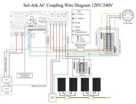
AC coupling involves wiring solar panels into an existing AC-coupled solution (such as microinverters, string inverters, or other battery-based inverters) and connecting that solution to your Sol-Ark inverter. This is primarily recommended for retrofit applications where existing equipment is already installed. If no system exists, DC coupling directly into the Sol-Ark MPPTs is recommended for better efficiency and control.
System Requirements and Limits
The maximum AC coupled input on all Sol-Ark inverters is 9.6kW. All AC coupled sources must be either UL 1741SA or UL 1741 certified to ensure the Sol-Ark can safely frequency shift to control production.
Maximum combined input (DC + AC) per model:
- 15K: 17kW DC + 19.2kW AC = 36.2kW Total
- 12K: 13kW DC + 3kW AC = 16kW Total
- 8K: 11kW DC + 4kW AC = 15kW Total
- 5K: 6.5kW DC + 5.5kW AC = 12kW Total
Connection Options
There are three primary locations to connect AC coupled solutions:
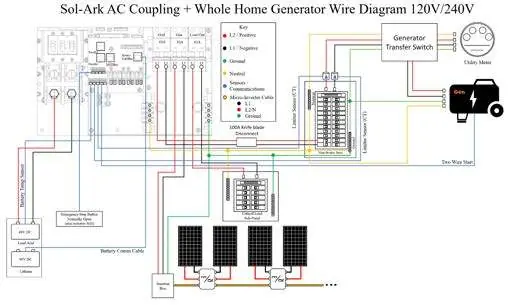
- Gen Breaker (Recommended): Provides monitoring capability (on outdoor models) and the most control, including accepting power during grid outages.
- Load Breaker: Accepts power during grid outages but does not allow monitoring of total production. Note: If using this method, the transfer time in a grid failure increases to 2 seconds.
- Grid Side (Main Service Panel): The AC coupled system remains independent. It will shut down during a grid outage and cannot produce power.
Wiring and Installation
Installation requires careful wiring to the appropriate breaker. Ensure that the Gen breaker is not used if the AC coupled system is connected to the Load side. When integrating a generator, the AC coupled solution must be on the Gen breaker, and the generator must be connected to the grid breaker (potentially requiring an ATS).


Programming Settings
Battery Setup - Smart Load:
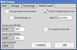
- For AC Coupled Input to Gen: Select this setting to tell the inverter to expect an AC coupled solution on the Gen breaker.
- AC couple on load side: Select this if connected to the Load breaker; this disables the Gen breaker.
- High Frz: Set to 62 Hz for UL 1741SA certified sources, or 65 Hz for UL 1741 certified sources.
- Smart Load OFF/ON Batt: These settings become setpoints for controlling the AC coupled solution during grid loss. Recommended: Set ON Batt to 60%-70% SOC and OFF Batt to 80%-90% SOC. Never set OFF Batt lower than ON Batt.
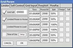
Grid Setup - Limiter:
When on-grid with AC coupling (not on the Grid side), the Grid Sell option must be enabled. If using Time of Use, ensure the "Grid Charge" box under the "Batt Setup" menu is NOT checked to avoid charging from the grid.
Off-Grid and Parallel Systems
It is not recommended to have only AC coupled inputs in an off-grid situation; DC coupling is preferred. For dark start capabilities, set the "Shutdown" value to around 20% SOC. When using parallel Sol-Ark inverters, ensure the AC coupled input is tied to all parallel inverters on the Gen breakers or the load panel.
Practical help
Common problems
AC coupled system shuts down during grid outage
If connected to the Grid side, the system is independent and will shut down. Connect to Gen or Load breaker for backup support.
Batteries overcharging during grid loss
Ensure Smart Load OFF Batt is set higher than Smart Load ON Batt. Never set OFF Batt lower than ON Batt.
Increased transfer time during grid failure
If AC coupling on the Load breaker, the transfer time increases to 2 seconds to protect batteries.
Before use
- Verify inverter is UL 1741 or 1741SA certified.
- Confirm AC coupled input does not exceed 9.6kW.
- Determine connection point (Gen Breaker is recommended).
- Ensure firmware/software is up to date.
- Check that Grid Charge is disabled if using Time of Use to prevent grid charging.
Specs in practice
- Max AC Coupled Input
- Hard limit of 9.6kW for all Sol-Ark inverters.
Images and diagrams
- Wiring diagrams show connections for Gen Breaker, Load Breaker, and Generator integration.
- Smart Load settings screen shows where to enable AC coupled input and set frequency limits.
Model compatibility
- Compatible with string inverters, microinverters, and other battery-based inverters.
- Requires UL 1741 or 1741SA certification for the AC coupled source.

Manual page author
David Miller
Documentation analyst
Organizes user manual content into clear summaries, with attention to model details, product context, and everyday usability.