Power / Solar Inverters
Installation Guide and User Manual for Sol-Ark 15K-2P-N Inverter
Comprehensive installation and user guide for the Sol-Ark 15K-2P-N solar inverter. Includes wiring diagrams, system configuration, battery setup, parallel system instructions, and troubleshooting.
Table of contents
Manual images
Click an image to enlargeQuick guide from the manual
The Sol-Ark 15K-2P-N is a 48V nominal residential solar inverter. Before operating, ensure the utility voltage is checked and the grid type is correctly programmed. The unit defaults to 120/240V Split-Phase at 60Hz. Always read the safety warnings, as improper installation can result in electrical shock, fire, or equipment damage.
Safety Instructions
- Qualified Personnel Only: Installation must be performed by qualified persons due to high risk of fire or electrocution.
- Grounding: The system must have ground and neutral connections, bonded only once in the circuit.
- PV Input: Do not exceed 500Voc on any MPPT. PV+/PV- are ungrounded.
- Battery Safety: Do not reverse battery polarity. Do not turn off the battery breaker while current is flowing.
- Fasteners: Do not use impact drivers on the unit.
Installation
The inverter is NEMA 3R/IP65 rated for indoor or outdoor use. Ensure at least 6 inches of vertical clearance for heat dissipation. Mount the unit level and protect the LCD screen from direct UV exposure.
Battery Integration
The system is a 48V nominal system. Batteries must be wired within the 43V-63V range. If using 12V batteries, do not exceed four in series. Use battery toroids on input wires as instructed. For parallel systems, all inverters must connect to a single battery bank.
PV Modules
The inverter features 3 MPPTs, each accepting up to 26A (self-limiting) and 500Voc. Strings in parallel on the same MPPT must have the same Voc.
Sensors and Accessories
CT sensors are required for "Limited Power to Home" and "Grid Peak-Shaving" modes. Arrows on CT sensors must point towards the grid. The system also supports an emergency stop button via dry contact pins (B, B).
User Interface and Settings
The touchscreen allows for comprehensive system configuration. Key menus include:
- Basic Setup: Time, date, and parallel system configuration.
- Battery Setup: Battery capacity, charge/discharge limits, and BMS communication settings.
- Limiter: Configures work modes like Grid Sell, Limited Power to Home, and Time of Use.
- Grid Setup: Grid type, frequency, and compliance settings.
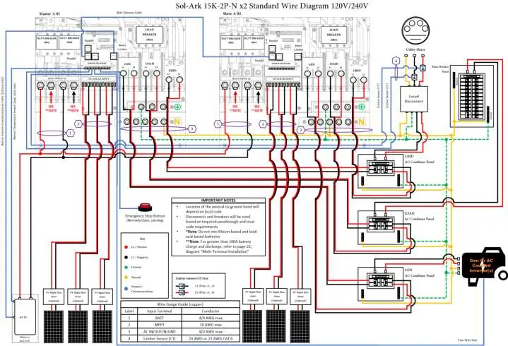
Parallel Systems
For parallel operation, all units must have the same software version. Assign one unit as "Master" (Modbus SN: 1) and others as "Slave" (Modbus SN: 2, 3, etc.). Use RJ45 cables for daisy-chain communication. DIP switches must be configured according to the specific parallel setup table provided in the manual.
Troubleshooting
If the system displays an error, consult the error code table. Common issues include:
- LCD not powering on: Check connections and power sources.
- Grid HM value negative: Limiter sensors are likely backwards or L1/L2 are swapped.
- System beeping: Check system alarms menu; ensure battery settings are correct.
- Grid Phase Wrong: Ensure phase sequence follows AB-BC-CA convention.
Practical help
Common problems
LCD not powering on
Check all connections (PV/Grid/Battery) and press the power button, touchscreen, or navigation buttons.
Panels connected but DC light is not on
Check string polarity on MPPT and ensure the PV DC disconnect is in the ON position. Minimum starting voltage is 125V.
Grid HM value is negative when it should be positive
Limiter sensors are backwards, L1/L2 sensors are swapped, or incorrectly wired. Try Auto Learn.
System is beeping
Check the System Alarms menu. If no battery is connected, ensure 'No Battery' is selected and 'Activate Batt' is disabled.
Grid Phase Wrong error
Ensure the phase sequence follows the AB-BC-CA convention. Check AC connections beyond the inverter.
Before use
- Verify utility voltage before turning ON the unit.
- Ensure ground is bonded to neutral only once in the circuit.
- Check battery polarity before connecting.
- Ensure all wire gauges comply with local electrical codes.
- Verify PV input voltage does not exceed 500Voc.
- Ensure CT sensors are installed with arrows pointing towards the grid.
Specs in practice
- Max PV Power
- 19,500W (STC)
- Max Output Current
- 62.5A
- Battery Voltage
- 48V nominal (43-63V operating range)
- Enclosure Rating
- IP65 / NEMA 3R (suitable for outdoor use)
- Backup Transfer Time
- 5ms
Images and diagrams
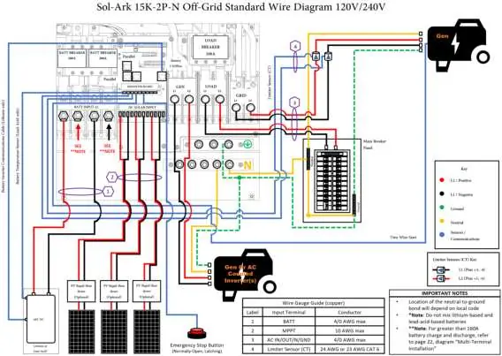
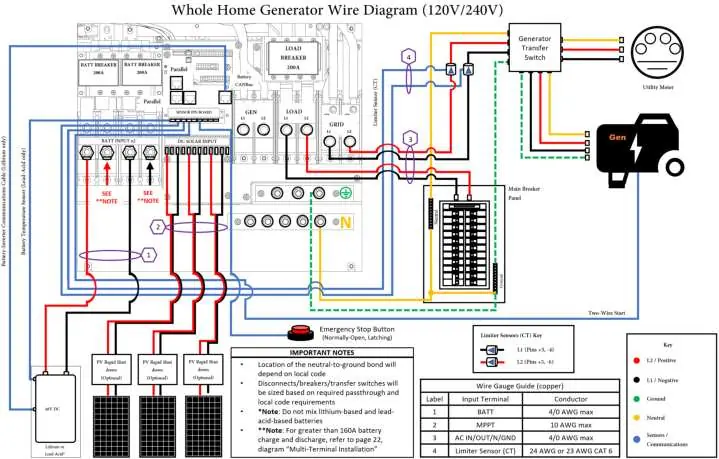
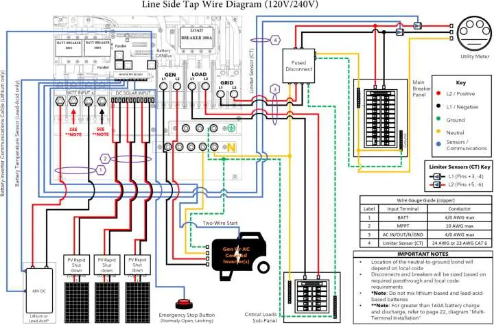
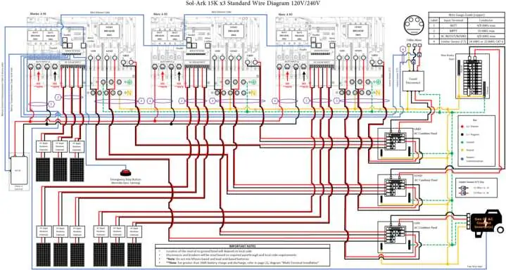
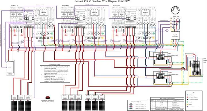
- Wiring Diagrams: Detailed schematics for off-grid, whole-home generator, and AC-coupled configurations are provided in section 7.
- CT Sensor Installation: Arrows on sensors must point towards the grid for correct measurement.
- Parallel Wiring: DIP switch configuration and daisy-chain communication are required for parallel systems.
Model compatibility
- Compatible with Lithium and Lead Acid batteries.
- Supports up to 12 units in parallel.
- Compatible with 120V/240V Split-Phase and 120V/208V 3-Phase systems.

Manual page author
Michael Turner
Technical manual editor
Reviews PDF manuals for structure, safety notes, and practical product details so readers can find the right information quickly.