Power / Solar Inverters
Wiring Diagrams for Sol-Ark 15K-2P-N Hybrid Inverter
Access official wiring diagrams for the Sol-Ark 15K-2P-N hybrid inverter. This guide provides detailed schematics for standard grid, line side tap, AC coupling, whole-home generator, off-grid, and parallel system installations.
Table of contents
Manual images
Click an image to enlargeImportant Safety and Installation Information
This document provides essential wiring diagrams for the Sol-Ark 15K-2P-N hybrid inverter. These diagrams are intended as general guidance. Installers must adhere to all local electrical codes and regulations. These diagrams are not exhaustive and should not be relied upon solely for permitting or warranty verification. Always seek professional advice when necessary and ensure compliance with established electrical standards.
Standard Wiring Configurations
The manual provides specific wiring schematics for various common installation scenarios:
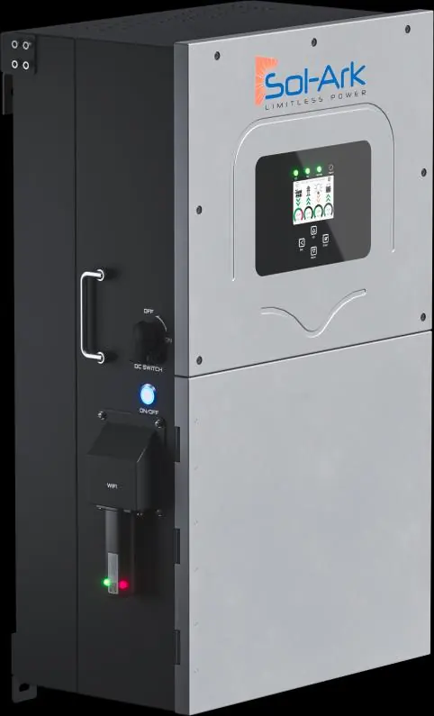
- Standard Wiring Diagram: The baseline configuration for grid-tied systems.
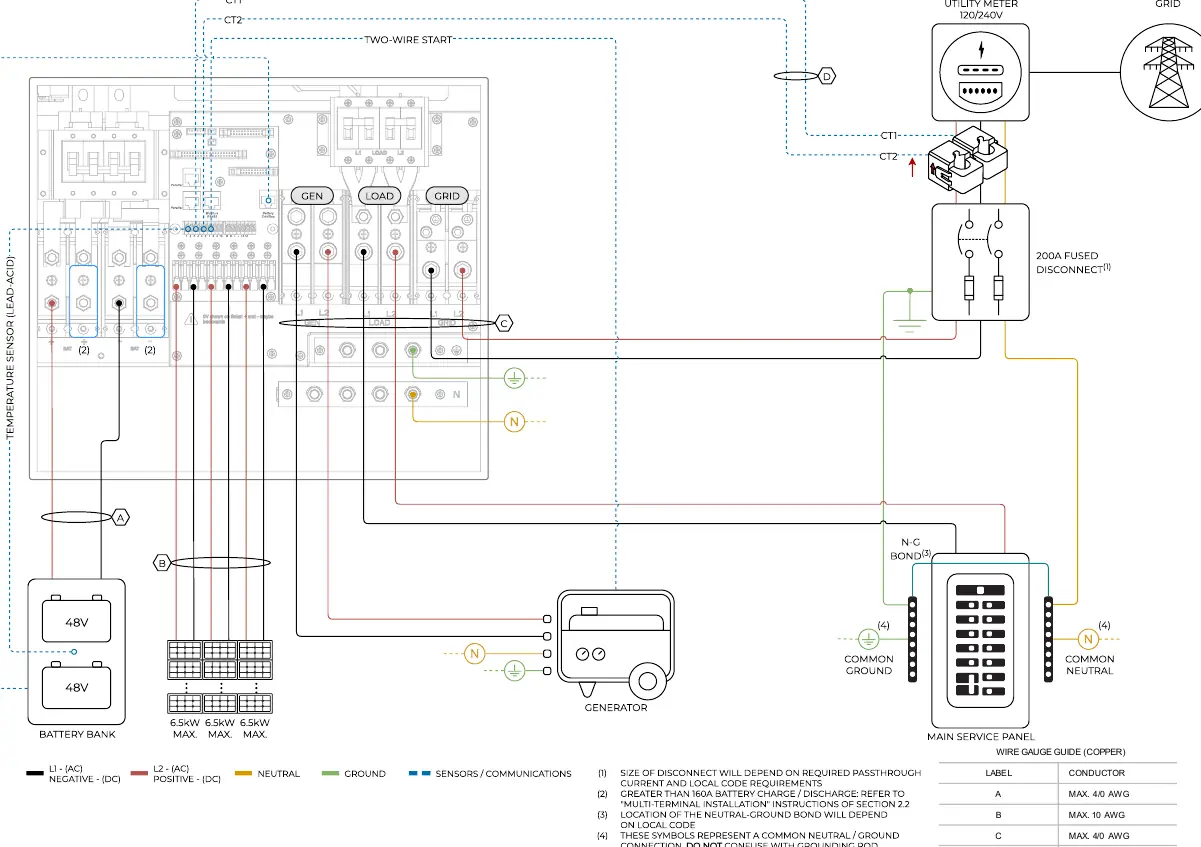
- Line Side Tap: Configuration for connecting the inverter to the line side of the service panel.
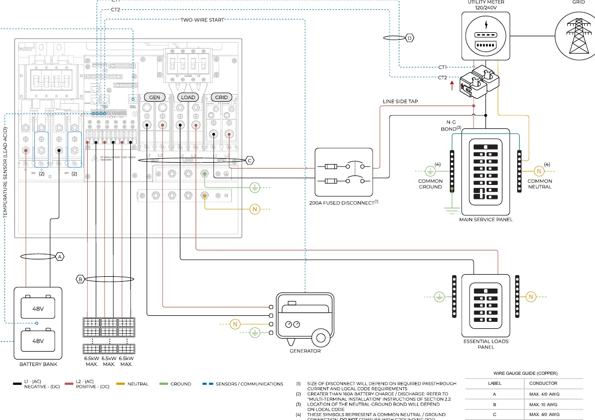
- AC Coupling: Diagrams are provided for AC coupling in the GEN port or the LOAD port, allowing for integration with other AC-coupled inverters.
Generator and Off-Grid Setups
Specific diagrams are included for systems utilizing backup power or operating independently of the grid:
- Whole-Home Generator: Wiring for systems integrating a whole-home generator via a transfer switch.
- Off-Grid: Configuration for systems operating without grid connection, including setups with secondary generators or AC-coupled inverters.
Parallel Inverter Configurations
For larger systems requiring multiple inverters, the manual provides detailed wiring diagrams for:
- 2 Parallel Inverters: Configurations for both 120/240V and 120/208V systems.
- 3 Parallel Inverters: Configurations for both 120/240V and 120/208V systems.
Note: Before powering up any Parallel System installation, you must refer to section 5 “Parallel Systems” in the main product manual.
Wire Gauge Guide
The following wire gauges (Copper) are specified for the connections labeled in the diagrams:
- A: Max 4/0 AWG
- B: Max 10 AWG
- C: Max 4/0 AWG
- D: 24 – 23 AWG CAT6
Practical help
Common problems
Incorrect Neutral-Ground Bond
The location of the neutral-ground bond depends on local code. Do not confuse this with the grounding rod connection.
Parallel System Startup Issues
Ensure you have consulted section 5 'Parallel Systems' in the main manual before powering up any parallel installation.
Incorrect Wire Gauge
Verify all conductors match the Wire Gauge Guide provided in the diagrams (e.g., 4/0 AWG for A and C, 10 AWG for B).
Before use
- Verify adherence to all local electrical codes and regulations.
- Select the correct wiring diagram based on your specific installation type (e.g., Standard, AC Coupling, Off-Grid).
- Ensure CT1 and CT2 are correctly oriented and connected.
- Check that all conductors (A, B, C, D) meet the specified wire gauge requirements.
- For parallel systems, ensure RJ45 parallel cables are properly installed between units.
Images and diagrams
- Diagram 01: Standard Wiring Diagram.
- Diagram 02: Line Side Tap configuration.
- Diagram 03-04: AC Coupling configurations.
- Diagram 05: Whole-Home Generator setup.
- Diagram 06: Off-Grid setup.
Model compatibility
- Supports 120/240V and 120/208V electrical systems.
- Compatible with lithium and lead-acid battery banks.
- Supports parallel operation for up to 3 inverters.

Manual page author
Michael Turner
Technical manual editor
Reviews PDF manuals for structure, safety notes, and practical product details so readers can find the right information quickly.