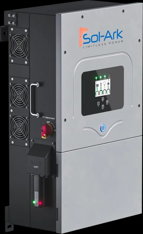
Power / Solar Inverters
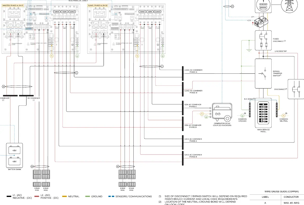
Wiring Diagrams for Sol-Ark 12K-2P-N Inverter
Comprehensive wiring diagrams and installation configurations for the Sol-Ark 12K-2P-N inverter, including standard, off-grid, generator, and parallel system setups.
Table of contents
Manual images
Click an image to enlargeImportant Information
This document provides essential wiring diagrams for the Sol-Ark 12K-2P-N inverter. Installers must adhere to all local electrical codes and regulations. These diagrams are intended for general guidance and should not be relied upon solely for permitting or warranty verification. Always consult with relevant authorities before proceeding with any installation.
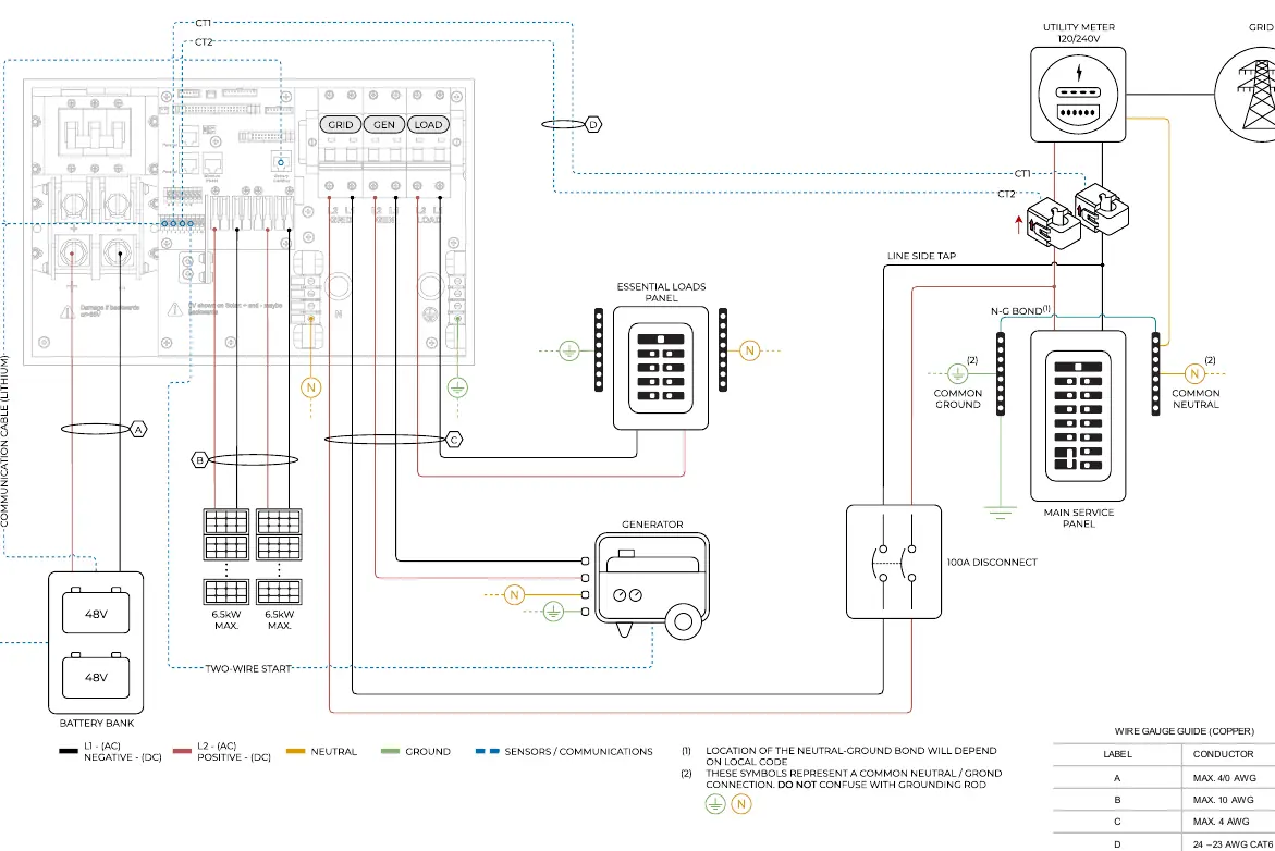
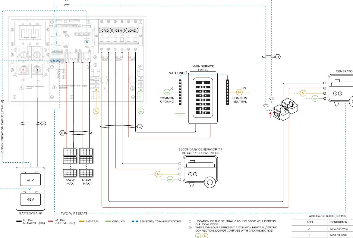
Wiring Diagrams
The manual includes specific wiring configurations for various installation scenarios:
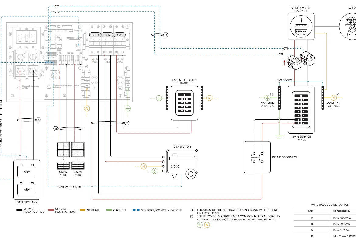
- Standard Wiring: Basic setup for grid-tied systems.
- Line Side Tap: Configuration for line side tap installations.
- AC Coupling: Diagrams for AC coupling in GEN and LOAD ports.
- Whole-Home Generator: Setup for integrating a whole-home generator.
- Off Grid: Configuration for off-grid applications.
- Parallel Systems: Detailed diagrams for 2 and 3 parallel inverters in 120/240V and 120/208V configurations.
Wire Gauge Guide
Always refer to the Wire Gauge Guide (Copper) provided on each diagram page to ensure the correct conductor size is used:
- Label A: Max 4/0 AWG
- Label B: Max 10 AWG
- Label C: Max 4 AWG
- Label D: 24-23 AWG CAT6
Parallel Systems Warning
Before powering up any Parallel System installation, you must refer to section 5 'Parallel Systems' in the main product manual for critical configuration steps.
Practical help
Before use
- Verify local electrical codes and regulations.
- Ensure the correct wiring diagram is selected for your specific installation (Standard, Off-Grid, Parallel, etc.).
- Use appropriate wire gauges as specified in the Wire Gauge Guide.
- Check for N-G bond requirements based on local code.
- Ensure all connections are secure and follow the diagram labels.
Specs in practice
- Wire Gauge A
- Max 4/0 AWG (Copper)
- Wire Gauge B
- Max 10 AWG (Copper)
- Wire Gauge C
- Max 4 AWG (Copper)
- Wire Gauge D
- 24-23 AWG CAT6
Images and diagrams
- Diagram 01: Standard Wiring
- Diagram 02: Line Side Tap
- Diagram 03: AC Coupling in GEN
- Diagram 04: AC Coupling in LOAD
- Diagram 05: Whole-Home Generator
Model compatibility
- Ensure compliance with local electrical codes.
- Parallel system installations require specific configuration (see section 5 of main manual).
- Neutral-ground bond location depends on local code.

Manual page author
Michael Turner
Technical manual editor
Reviews PDF manuals for structure, safety notes, and practical product details so readers can find the right information quickly.