Power / Solar Inverters
Installation Guide and User Manual for Sol-Ark 15K-2P Outdoor Hybrid Inverter
Comprehensive installation guide and user manual for the Sol-Ark 15K-2P Outdoor hybrid inverter. Includes detailed wiring diagrams, system setup, programming instructions, troubleshooting, and maintenance procedures.
Table of contents
Manual images
Click an image to enlargeQuick Guide from the Manual
The Sol-Ark 15K-2P Outdoor is a hybrid inverter designed for residential solar power systems. Before installation, read the entire manual to prevent electrical shock, serious injury, or death. Only qualified persons should install this equipment. Ensure the system has proper Ground and Neutral connections, bonded only once in the circuit. Do not connect the grid to the Load Output Terminal Block, and do not reverse battery polarity.
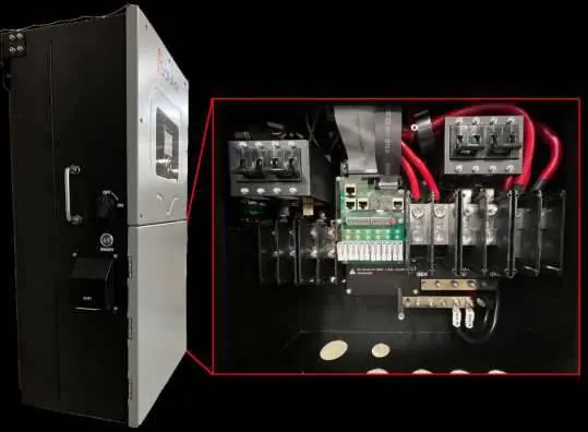
Inverter Components
The unit features an LCD touch screen, PV disconnect switch, ON/OFF button, Wi-Fi dongle input, battery breakers, communication ports, and various terminal blocks for Grid, Load, and Generator connections. Refer to the physical installation section for a detailed layout of these components.
Physical Installation
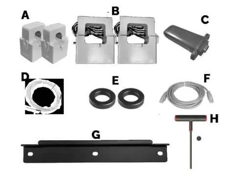
Mount the unit on a wall using the provided French Cleat, ensuring it is level and protected from excessive UV exposure. The system weight is 135lbs (61.24kg). Ensure 2" minimum horizontal clearance and 6" minimum vertical clearance for cooling.

Integrating Batteries
The Sol-Ark 15K is a 48V system. Connect batteries to the terminal blocks, ensuring the built-in battery disconnect is OFF during connection to prevent arcing. Use the included toroids on battery input cables. Lithium batteries do not require a temperature sensor.
Connecting Solar Panels
The inverter has triple MPPTs for three separate PV input pairs. Maximum PV input is 19.5kW. Ensure parallel strings per MPPT are the same voltage. Ground the panel mounts/frames to an external ground via 12AWG wire.
Integrating a Generator
The system supports 240V generators. Connect to the "GEN" terminal block. For generators larger than 19.2kW, connect to the "GRID" terminal block. Ensure the generator is compatible with two-wire start if using automatic generator start features.
Programming and Setup
Use the LCD touchscreen to configure the system. The main menus allow for basic setup, battery configuration, grid settings, and system alarms. Key settings include:
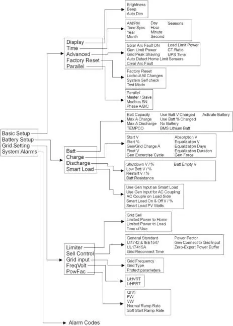
- Battery Setup: Define battery capacity, charge/discharge rates, and charging voltages.
- Grid Setup: Configure grid frequency, grid type, and power modes (e.g., Grid Sell, Limited Power to Home, Time of Use).
- Limiter Sensors (CTs): Essential for Limited Power to Home and Peak Shaving modes. Install on L1 and L2 upstream of the main panel.
Troubleshooting
If the system displays an error, consult the error code table in the manual. Common issues include:
- LCD not powering on: Check PV/Grid/Battery connections.
- Grid Phase Wrong: Indicates a phasing issue; check L1/L2 wiring between Grid and Load.
- Panels not producing: Verify PV voltage (150V-425V) and polarity.
- System beeping: Check the alarms menu for specific fault codes.
For technical support, contact Sol-Ark at 1-972-575-8875 or email [email protected].
Practical help
Common problems
LCD not powering on
Check all connections; at least one power source (PV, Grid, or Battery) is required. Press the power button or touchscreen.
Grid Phase Wrong error
Indicates a phasing issue. Measure L1 to L1 and L2 to L2 between Grid and Load breakers; you should read 0V AC. Correct wiring until this is achieved.
Panels not producing power
Check that PV voltage is between 150V-425V, the PV disconnect is ON, and polarity is correct.
System is beeping
Check the system alarms menu to identify the fault. If no battery is connected, ensure 'No Battery' is selected in the Battery menu.
Before use
- Verify PV voltage is no higher than 500Voc.
- Ensure Ground and Neutral are bonded only once in the circuit.
- Check battery polarity before connecting to avoid damage.
- Install CT sensors on L1 and L2 upstream of the main panel.
- Ensure all battery lugs are tightened to 90 IN Lbs.
- Confirm the LCD is protected from direct sunlight.
Specs in practice
- Max PV Input
- 19.5kW total; 6.5kW per MPPT.
- Continuous AC Power
- 15kW (62.5A at 240V).
- Battery Voltage
- 48V nominal system (43V-63V range).
- Enclosure Rating
- IP65 / NEMA 3R (suitable for outdoor installation).
Images and diagrams
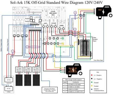
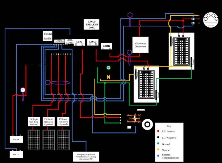
- Wiring Diagrams: Provided for various scenarios including Off-Grid, Grid-Tie, and Parallel systems.
- Sensor Pin Out: Details connections for battery temp, CT sensors, generator start, and emergency stop.
Model compatibility
- Generators: Supports 240V generators; GEN input does not support 3-phase generators.
- Batteries: 48V system; Lithium batteries do not require a temperature sensor.
- Parallel Systems: Require a joint battery bank and specific dipswitch settings.

Manual page author
David Miller
Documentation analyst
Organizes user manual content into clear summaries, with attention to model details, product context, and everyday usability.