Power / Solar Inverters
Sol-Ark PCS 200A Power Control System Application Note
A technical guide for the Sol-Ark PCS 200A, covering Power Control System (PCS) design, CT placement, NEC 705.13 compliance, and installation best practices for whole-home and large-load applications.
Quick answers from the manual
Quick answer
- The Sol-Ark PCS 200A application note provides guidance on designing and commissioning systems with 200A pass-through, focusing on Power Control System (PCS) compatibility, NEC 705.13 compliance, and correct CT placement for whole-home applications. p. 1
Key actions
- Install CTs on ungrounded service conductors p. 5
- Configure PCS settings in the inverter UI p. 6
Problems and fixes
PCS blind to house loads
Move CTs to service conductors.
p. 7Show 1 more answers Show less
Where to find it in the PDF
- Key Concepts and Capabilities p. 1
- CT Hardware and Installation Details p. 5
Table of contents
Manual images
Click an image to enlargeKey Concepts and Capabilities
This application note provides guidance on designing and commissioning Sol-Ark inverters with 200 A pass-through. The primary goal is to maximize Power Control System (PCS) compatibility for whole-home and large-load applications, ensuring code-compliant interconnections (NEC 705.13).
- 200 A Pass-Through: Allows the inverter to be placed in-line with a standard 200 A residential service feeder.
- PCS (Power Control System): Uses grid-sense Current Transformers (CTs) to dynamically limit export and cap back-feed currents, satisfying utility non-export rules.
- Self-Consumption Optimization: Prioritizes serving local loads from PV/battery, importing only deficit power from the grid.
Design Flexibility
The PCS feature allows for flexible interconnection methods:
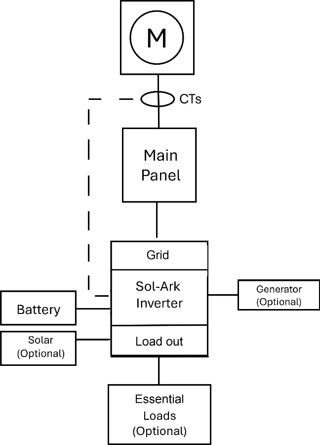
- Breaker-Fed (Load-Side): Enables interconnection with a larger breaker than traditional 120% busbar rules allow, provided the system is accepted by the AHJ/utility.
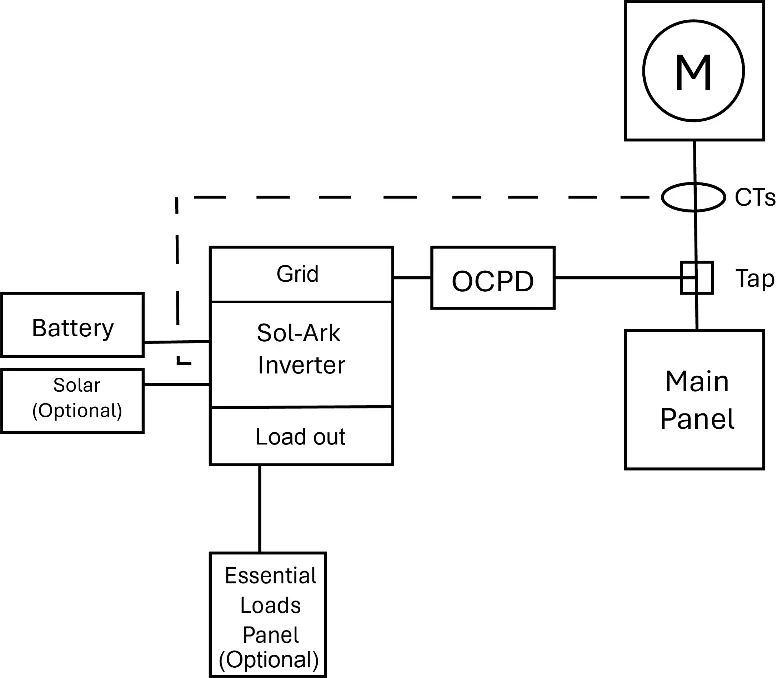
- Supply-Side (Line-Side Tap): Useful when the main load center cannot accept additional back-feed. The PCS still controls export at the service point.
- Whole-Home 200 A Pass-Through: The inverter acts as the gatekeeper between the utility and the house, ensuring non-export and keeping service conductors within ratings.
CT Hardware and Installation Details
Proper CT placement is critical for the system to function correctly. Follow these guidelines:
- Conductors: Install CTs only on ungrounded (hot) service conductors; never on neutrals or grounds.
- Orientation: Follow the arrow/labeling. The arrow should point toward the load (the grid for service conductors).
- Location: Place CTs on service conductors upstream of all load panels for global control.
- Lead Routing: Keep CT leads away from high-noise cables, use twisted pairs, and respect maximum lead length.
- Verification: Confirm correct installation by checking that a known resistive load (1-2 kW) displays as an import in the inverter UI.
Inverter Settings for PCS
To maximize PCS performance, configure the following settings:
- Mode: Set to Self-Consumption / Priority Load.
- Export Limit: Set to Zero (non-export) or a specific kW/kVA cap as allowed by the utility.
- Grid Charge Windows (TOU): Configure to allow off-peak charging to raise State of Charge (SoC) for on-peak discharge.
- SoC Reserves: Maintain a UPS reserve (e.g., 20-40%) while enabling peak shaving above that level.
Troubleshooting
If the system is not behaving as expected, check the following:
- PCS blind to house loads: Ensure CTs are on the service conductors, not just the inverter feeder.
- Export shows as import: This indicates reversed CT polarity; flip the CT orientation.
- Generator back feed risk: Never allow export toward a generator; use an approved transfer switch/ATS and place CTs on load conductors.
Practical help
Common problems
PCS blind to house loads
CTs are on the wrong conductors (e.g., only on inverter feeder). Move CTs to service conductors.
Export shows as import
Reversed CT polarity. Flip CT orientation.
Generator back feed risk
Never allow export toward a generator; use approved transfer/ATS and place CTs on the load conductors, not generator or utility conductors.
Before use
- Verify AHJ/utility acceptance for NEC 705.13 PCS.
- Ensure CTs are installed on ungrounded (hot) service conductors.
- Confirm CT orientation (arrow toward the load/grid).
- Keep CT leads away from high-noise cables.
- Verify system with a known resistive load (1-2 kW) during commissioning.
Show more Show less
Specs in practice
- PCS (Power Control System)
- Uses grid-sense CTs to limit export and cap back-feed currents dynamically.
- 120% Busbar Rule
- Traditional calculation limiting PV/ESS breaker size; PCS allows bypassing this with AHJ approval.
- CT (Current Transformer)
- Device used to measure net import/export at the service point.
Images and diagrams
- Breaker-Fed/Load-Side: CTs measure whole-home net import/export.
- Supply-Side/Line-Side Tap: CTs must be on the utility side of the tap to capture net service exchange.
- Whole-Home 200A Pass-Through: Inverter acts as the gatekeeper between utility and house.
Model compatibility
- Applies to Sol-Ark Limitless 18K-2P-LV, Limitless 15K-LV, 30K-3P-208V, and 60K-3P-480V.
- Requires AHJ/utility acceptance for NEC 705.13 PCS control schemes.

Manual page author
David Miller
Documentation analyst