Power / Solar Inverters
User Manual for Sol-Ark 5K, 8K, 12K, 15K Inverter
Quick guide for connecting and configuring Sol-Ark 5K, 8K, 12K, and 15K inverters with Pytes E-BOX batteries. Includes cable wiring, DIP switch settings, and inverter programming parameters.
Table of contents
Manual images
Click an image to enlargeQuick guide from the manual
This document provides instructions for integrating Sol-Ark 5K, 8K, 12K, and 15K inverters with Pytes E-BOX batteries. It covers physical cable connections, communication setup, and software configuration required for the system to operate correctly.
Connecting Cables
Proper cable sizing and communication connections are essential for system safety and performance.
- Power Cables: Use 4/0 gauge power cables for the Sol-Ark 15K model. Use 3/0 gauge power cables for the 8K and 12K models. Connect these between the inverter and the battery or busbars.
- Communication Cables: A standard ethernet cable is used for communication between the inverter and the Pytes E-BOX battery, as the pin assignments are compatible.
DIP Switch Settings
Before connecting communication cables, configure the DIP switches on every master battery. Refer to the specific DIP switch diagram provided in the manual to ensure the correct switch positions are set.
Programming the Inverter
Once the physical connections are made, configure the inverter settings via the touchscreen interface:
- Press the gear icon on the top right of the screen.
- Select the Battery Setup menu.
Battery Parameters
In the Battery Setup menu, configure the following parameters:
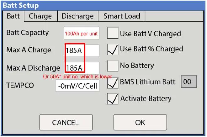
- Batt Capacity: Set to 100Ah per unit.
- Max A Charge/Discharge: For 8K/12K models, the max is 185A. For the 15K model, the max is 275A. Enter the lower value of either the inverter's max amps or 50A multiplied by the number of battery units.
- Settings: Select Use Batt% Charged.
- BMS Lithium Batt: Enable this and set the value to 00.
- Activate Battery: Turn this setting ON.
Note: Enabling BMS Lithium Batt 00 will automatically adjust and lock certain values (like temperature coefficients). Ignore these locked values as the BMS is in control.
Charge and Discharge Tab Configuration
Navigate to the Charge and Discharge tabs within the Battery Setup menu to configure operational limits:
Charge Tab
- Start%: 15%
- A: Same as the Max A Charge value set in the Battery tab.
- Float V: 55.6V
- Absorption V: 56V
- Equalization V: 56V
Discharge Tab
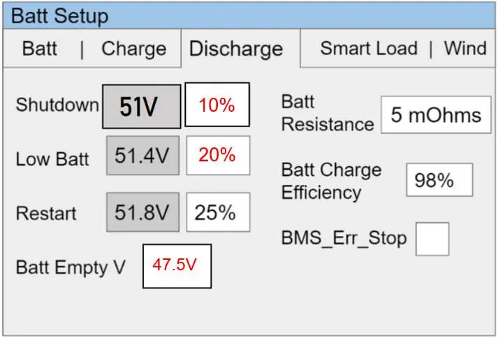
- Shutdown: 10%
- Low Batt: 20%
- Batt Empty: 47.5V
Confirming Communication
After programming, verify that the inverter and battery are communicating. Successful communication is indicated when battery data appears in the header section of the system setup screen.
Practical help
Common problems
Communication failure between inverter and battery
Check that the ethernet cable is securely connected to the CAN port on the battery and the Battery CANBus port on the inverter. Verify DIP switch settings on the master battery.
Incorrect charging behavior
Ensure 'Use Batt% Charged' is selected and 'BMS Lithium Batt' is enabled with a value of '00'.
Before use
- Verify 4/0 gauge power cable for 15K model.
- Verify 3/0 gauge power cable for 8K/12K models.
- Ensure standard ethernet cable is used for communication.
- Set DIP switches on the master battery.
- Confirm battery capacity is set to 100Ah per unit.
Specs in practice
- Max A Charge/Discharge
- The maximum amperage allowed. Use the lower value of either the inverter's limit (185A for 8K/12K, 275A for 15K) or 50A multiplied by the number of battery units.
- BMS Lithium Batt
- Must be set to '00' to allow the BMS to control battery parameters.
- Float/Absorption/Equalization V
- Voltage settings for charging stages; set to 55.6V, 56V, and 56V respectively.
Images and diagrams
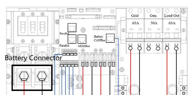
- Figure 2.1: Shows the battery connector wiring between the inverter and battery/busbars.
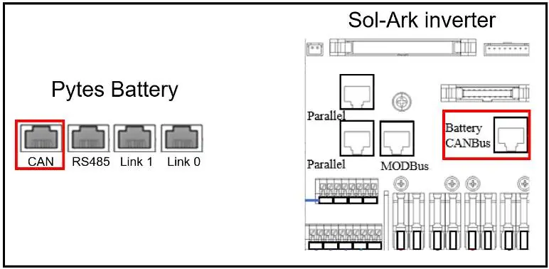
- Figure 2.4: Illustrates the CANBus cable connection between the Pytes battery CAN port and the Sol-Ark inverter Battery CANBus port.
- Figure 2.6: Displays the Battery Setup menu interface for inputting charge and discharge parameters.
Model compatibility
- Compatible with Pytes E-BOX batteries.
- Sol-Ark inverter pin assignment is the same as Pytes E-BOX battery.

Manual page author
David Miller
Documentation analyst
Organizes user manual content into clear summaries, with attention to model details, product context, and everyday usability.