Automotive / Car Audio
User Manual for SounDigital 3000.1 EVO6 Amplifier
Quick guide for the SounDigital 3000.1 EVO6 amplifier. Includes installation steps, wiring diagrams, gain settings, safety instructions, and troubleshooting.
Table of contents
Manual images
Click an image to enlargeQuick Guide
This manual provides essential instructions for the SounDigital 3000.1 EVO6 amplifier. Key points for a successful installation include:
- Safety First: Always disconnect the negative battery terminal before starting any installation to prevent short circuits and injury.
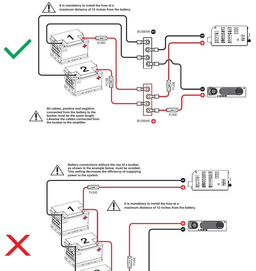
- Fuse Placement: It is mandatory to install a fuse or circuit breaker within 12 inches (30cm) of the battery.
- Cable Quality: Use only OFC (Oxygen Free Copper) cables. Avoid Copper-clad aluminum wire (CCAW).
- Ventilation: Ensure the amplifier is installed in a ventilated area and do not block side ventilation windows.
- Voltage: This equipment is designed for automotive DC voltage batteries between 12.6V and 14.4V.
Safety Instructions
To avoid injury or damage to the equipment, follow these safety guidelines:
- Installation must be performed by a qualified professional.
- Wear appropriate PPE (gloves, safety glasses) during installation.
- When passing cables through metallic walls, use rubber O-rings to prevent cutting and short circuits.
- Ensure the amplifier is fixed firmly and not attached to metallic parts of the vehicle to avoid ground loops.
- Be cautious when drilling holes in the vehicle to avoid fuel tanks, brake lines, or electrical cables.
- The amplifier can reach temperatures over 60°C (140°F); allow it to cool before touching.
Panels Description
The amplifier features two main panels:
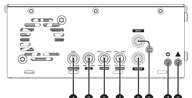
- Audio Inputs and Controls: Includes RCA inputs, Bass Boost (0-12dB at 50Hz), Gain control, Low Pass filter (80Hz-20kHz), and High Pass filter (5Hz-80Hz). It also features Power (Blue) and Clip (Yellow) LED indicators.
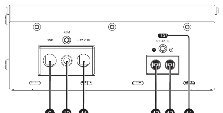
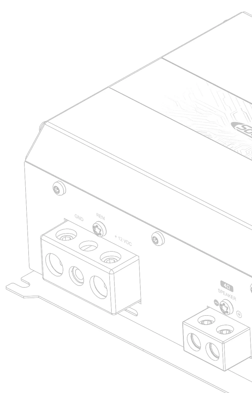
- Power Inputs and Audio Outputs: Includes terminals for GND (Negative), REM (Remote), +12VDC (Positive), and Speaker output connectors.
Installation Sequence
- Disconnect the negative battery terminal.
- Fix the amplifier in a location with easy access to connectors.
- Install power cables from the battery to the fuse holder, keeping the fuse in the "OFF" position.
- Connect power cables to the amplifier, observing correct polarity.
- Connect the ground cable to the vehicle chassis and battery negative; ensure it is as short as possible.
- Install signal input cables away from power cables.
- Connect RCA cables to the head unit and amplifier.
- Connect audio output cables to speakers, respecting polarity.
- Connect the remote cable (1.5mm² / 15 AWG or thicker) to the amplifier's REM terminal.
- Verify all connections for short circuits before powering on.
- Reconnect the battery ground and switch on the system.
Electrical Dimensioning
Proper electrical dimensioning is critical for performance. The recommended cable sections are:
- Power/Ground Cable: 35mm² (2 AWG).
- Speaker Cable: 6.0mm² (9 AWG) for 1Ω, 4.0mm² (11 AWG) for 2Ω, 2.5mm² (13 AWG) for 4Ω.
- Remote Cable: 1.5mm² (15 AWG).
Gain Setting
To set the gain correctly:
- Turn gain control to minimum.
- Disconnect output cables.
- Set source unit volume to 3/4.
- Set Bass Boost to 0dB, High Pass to 5Hz, and Low Pass to 20kHz.
- Use a 60Hz sine wave test tone.
- Increase gain until the "CLIP" LED starts blinking, then back off slightly until it remains off.
Bass Boost and Crossover Setup
- Bass Boost: Adjustable from 0 to +12dB at 50Hz.
- Crossovers: Use the High Pass and Low Pass filters to create a bandpass filter. The High Pass filter (5Hz-80Hz) cuts low frequencies, while the Low Pass filter (80Hz-20kHz) cuts high frequencies.
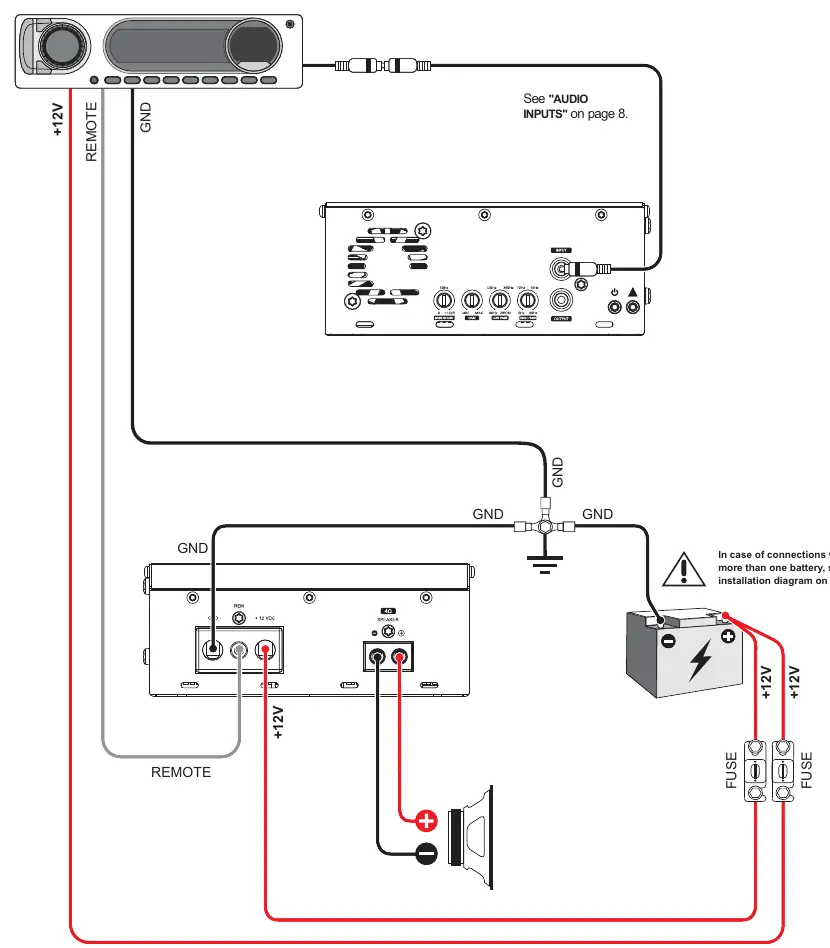
Wiring and Battery Connection
For systems with multiple batteries, use positive and negative busbars. Ensure all cables from the battery to the busbar and from the busbar to the amplifier are of the same length to maintain efficiency. Avoid connecting batteries without a busbar.
Troubleshooting
- Amplifier does not turn on: Check power and remote signal cable connections.
- Blue LED flashes: Check battery, cables, and fuse holder; ensure voltage is within range.
- Yellow LED flashes: Check for short circuits in output wiring or speakers; verify minimum impedance.
- Abnormal noise: Check RCA cables, ground quality, and spark plug wires.
Technical Specifications
The 3000.1 EVO6 operates with a frequency response of 5Hz ~ 20kHz and an SNR of 92dB. It requires a minimum 150A fuse and 150Ah battery. Refer to the full technical table in the manual for specific power ratings at 1Ω, 2Ω, and 4Ω.
Practical help
Common problems
Amplifier does not turn on
Check if the power and remote signal cables are connected correctly.
Blue LED flashes
Check the battery, cables, and fuse holder. Ensure the battery and cables are sized according to the parameter table.
Yellow LED flashes
Check for a short circuit in the output wiring or speakers. Verify the minimum recommended impedance.
Abnormal noise from speakers
Check for defective RCA cables, ground faults, or interference from spark plug wires.
Before use
- Disconnect the negative battery terminal before starting installation.
- Ensure the fuse/circuit breaker is installed within 12 inches (30cm) of the battery.
- Use only OFC (Oxygen Free Copper) cables; do not use CCAW.
- Verify battery voltage is between 12.6V and 14.4V.
- Ensure the amplifier is installed in a ventilated area.
- Wear safety glasses and gloves during installation.
Specs in practice
- Input Sensitivity
- The minimum input voltage required for the amplifier to reach full power output.
Images and diagrams
- Wiring Diagram: Illustrates the connection of power, ground, remote, and RCA cables.
- Battery Connection Diagram: Shows the correct use of busbars for multiple battery banks to ensure efficiency.
Model compatibility
- Requires 12.6V - 14.4V DC automotive electrical system.
- Minimum speaker load depends on the specific model version (1Ω, 2Ω, or 4Ω).

Manual page author
David Miller
Documentation analyst
Organizes user manual content into clear summaries, with attention to model details, product context, and everyday usability.