Automotive / Car Audio
Owner's Manual for VIBE Powerbox 100.4M Car Amplifier
Quick guide for the VIBE Powerbox 100.4M car amplifier. Includes installation steps, wiring diagrams, connection instructions, and technical specifications.
Table of contents
Manual images
Click an image to enlargeQuick guide from the manual
This manual provides essential installation and operation instructions for the VIBE Powerbox 100.4M amplifier. Key safety requirements include mounting the unit in a dry location on a solid surface, ensuring adequate airflow (at least two inches around the casing), and never mounting the unit upside down to prevent overheating. Always disconnect the fuse until the installation is complete.
Mounting Guidelines
The amplifier is designed for a swift installation routine. Ensure the chosen location is dry and solid. Proper ventilation is critical; ensure there is at least two inches of space around the exterior of the casing to allow for effective cooling. Do not mount the amplifier upside down.
Power Connections
Proper power delivery is essential for performance:
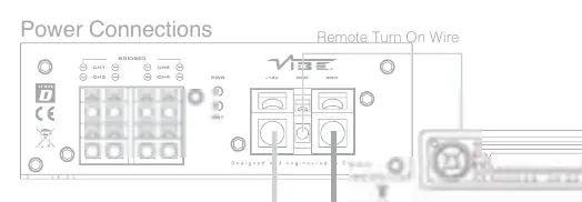
- Use at least 8 gauge cable for both power and ground connections.
- The power cable must be taken directly from the battery.
- Install a fuse or circuit breaker inline with the power cable, no further than 18 inches from the battery.
- The ground cable should be connected directly to the vehicle chassis at a bare metal point. Keep the cable length to an absolute minimum.
- Do not use the vehicle's seatbelt anchor point for the ground connection.
Inputs and Auto Turn On
The amplifier supports both low-level (RCA) and high-level (speaker) inputs. Do not connect both input types simultaneously. The PowerBox features an 'Autosense' circuit, which allows the amplifier to switch on and off automatically when using high-level inputs, eliminating the need for a remote turn-on wire. If using low-level (RCA) inputs, a remote turn-on wire from the head unit is required.
Terminals and Connections
The amplifier features various controls for fine-tuning audio:

- Gain Control: Used to match the input signal of the source to the amplifier channels.
- Crossover Mode Select: Choose between Full Range (FR), High Pass Filter (HPF), or Low Pass Filter (LPF).
- Filter Controls: High pass filter is adjustable between 100Hz and 500Hz; low pass filter is adjustable between 40Hz and 4kHz.
- Input Mode Switch: Selects between 2 or 4 channel signal input.
- Power/Protect LED: A green light indicates normal operation, while a red light indicates the amplifier is in protection mode.
Wiring Configurations
The amplifier supports different wiring setups depending on your speaker configuration:
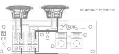
- 4 Channel Configuration: Allows for 2Ω minimum impedance per channel.
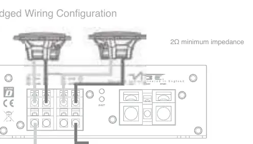
- Bridged Wiring Configuration: Allows for 4Ω minimum impedance for bridged channels.
Technical Specifications
The Powerbox 100.4M features a 4-channel configuration with a frequency response of 10Hz - 30kHz. It utilizes a Mini Class D topology. RMS power output is 4 x 100 watts at 4Ω stereo, 4 x 120 watts at 2Ω stereo, or 2 x 240 watts at 4Ω mono.
Technical Support
For UK technical enquiries, call 09067031420 (Monday - Friday, 9.00am - 5.30pm GMT). For international support, please visit the official website at www.vibeaudio.co.uk/contact.
Official resources from the manual
Practical help
Common problems
Amplifier overheating
Ensure the amplifier is not mounted upside down and has at least two inches of clear space around the casing for airflow.
Amplifier not turning on
Check the fuse near the battery and ensure the ground connection is secured to bare metal on the vehicle chassis.
Audio interference/noise
Run RCA cables on the opposite side of the vehicle from the power cables to avoid picking up interference.
Before use
- Use at least 8 gauge cable for power and ground connections.
- Install a fuse or circuit breaker inline with the power cable, no further than 18 inches from the battery.
- Ensure the ground cable is connected directly to the vehicle chassis (bare metal).
- Do not connect both high-level and low-level inputs at the same time.
- Verify the minimum impedance for your wiring configuration (2Ω for 4-channel, 4Ω for bridged).
Specs in practice
- RMS @ 4Ω Stereo
- Continuous power output per channel when driving 4-ohm speakers.
- Frequency Response
- The range of audio frequencies the amplifier can reproduce (10Hz - 30kHz).
Images and diagrams
- Power Connections: Shows the +12V, REM, and GND terminal connections with fuse and battery placement.
- 4 Channel Wiring: Illustrates connecting four separate speakers to the amplifier.
- Bridged Wiring: Illustrates combining channels to drive a single speaker at higher power.
Model compatibility
- Autosense feature allows auto turn-on with high-level inputs without a remote wire.
- Compatible with head units having either low-level (RCA) or high-level (speaker) outputs.

Manual page author
David Miller
Documentation analyst
Organizes user manual content into clear summaries, with attention to model details, product context, and everyday usability.