Automotive / Car Audio
JBL CLUB 1000SSL and 1200SSL Subwoofer Owner's Manual
Quick guide for installing and connecting JBL CLUB 1000SSL and 1200SSL shallow subwoofers. Includes wiring diagrams, mounting instructions, and technical specifications.
Table of contents
Manual images
Click an image to enlargeQuick Guide
This manual provides installation and connection instructions for the JBL CLUB 1000SSL and 1200SSL shallow subwoofers. For optimal performance, professional installation is recommended. Always disconnect the vehicle's negative battery terminal before beginning any electrical work.
Installation
Choose a mounting location that does not interfere with cargo, fold-down rear seats, or the trunk lid. The best location is typically a corner of the trunk or cargo area.
- Safety: Always wear protective eyewear when using tools.
- Clearance: Check both sides of the mounting surface to ensure screws or wires do not puncture brake lines, fuel lines, or wiring harnesses.
- Preparation: Use a utility knife to remove fabric or vinyl before drilling to prevent material from snagging on drill bits.
- Mounting: Secure the enclosure firmly to the mounting surface.
Speaker Connections
Connect the + and - terminals on the enclosure to the amplifier's outputs, ensuring correct polarity. Use at least 4mm² (11 AWG) speaker wire for these connections.
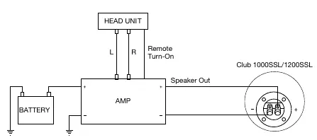
The system requires a connection from the Head Unit to the Amplifier, and from the Amplifier to the Subwoofer enclosure. Ensure the remote turn-on wire is connected to the amplifier.
Specifications
CLUB 1000SSL: 10" (250mm) Aluminum Driver, 350W RMS (1050W peak), 2 ohms impedance, 35Hz - 400Hz frequency response.
CLUB 1200SSL: 12" (300mm) Aluminum Driver, 400W RMS (1200W peak), 2 ohms impedance, 30Hz - 400Hz frequency response.
General Care
Clean the loudspeaker using only a damp cloth. Do not use any cleaners or solvents. This product is designed for mobile applications and is not intended for connection to mains power.
Manufacturer information
JBL
Practical help
Common problems
Box damage during installation
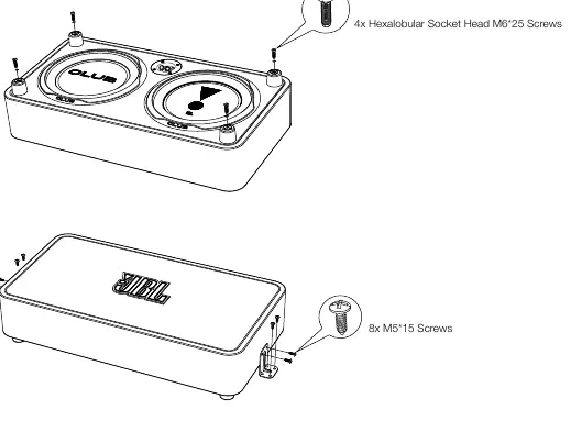
Ensure you use the correct screws. Use M6*25 screws for the top mounting points and M5*15 screws for the side brackets.
No sound or distorted sound
Check amplifier settings, ensure proper polarity on speaker connections, and verify the remote turn-on wire is active.
Before use
- Disconnect the negative (-) lead from the vehicle's battery.
- Wear protective eyewear.
- Check for brake lines, fuel lines, and wiring harnesses behind the mounting surface.
- Ensure electrical connections are secure and properly insulated.
- Verify the mounting location does not interfere with cargo or vehicle operation.
Specs in practice
- Power Handling (RMS)
- The continuous power the subwoofer can handle without damage.
- Nominal Impedance
- The electrical load (2 ohms) the subwoofer presents to the amplifier.
Images and diagrams
- Wiring Diagram: Illustrates the connection path from the Head Unit to the Amplifier, and from the Amplifier to the Subwoofer terminals.
- Mounting Diagram: Shows the specific screw types (M6*25 and M5*15) and their locations on the enclosure.
Model compatibility
- Designed for mobile applications only.
- Not intended for connection to mains power.
- Requires at least 4mm² (11 AWG) speaker wire.

Manual page author
Michael Turner
Technical manual editor
Reviews PDF manuals for structure, safety notes, and practical product details so readers can find the right information quickly.