Automotive / Car Audio
SounDigital 800.1 EVO 5 Mono Amplifier Owner's Manual
Quick guide for the SounDigital 800.1 EVO 5 mono car audio amplifier. Includes installation steps, wiring diagrams, gain adjustment procedures, and technical specifications.
Table of contents
Manual images
Click an image to enlargeQuick guide from the manual
This manual provides essential instructions for the SounDigital 800.1 EVO 5 mono amplifier. Key requirements include a battery voltage between 12.6V and 14.4V, the use of OFC (Oxygen Free Copper) cables, and a 40A fuse installed within 12 inches of the battery. Do not use RCA and High Level inputs simultaneously.
Safety instructions
- Disconnect the negative battery terminal before starting any installation.
- Ensure the amplifier is installed in a ventilated area, away from water, dirt, or humidity.
- Avoid mounting the amplifier on metallic parts of the vehicle to prevent ground loops.
- Use appropriate PPE (gloves, safety glasses) during installation.
- The amplifier can reach temperatures over 60°C/140°F; allow it to cool before touching.
Installation sequence
- Mount the amplifier securely with access to connectors.
- Install power cables from the battery to the fuse holder (max 12 inches/30cm from battery).
- Connect power cables to the amplifier, observing polarity.
- Connect the ground cable to the vehicle chassis, ensuring it is as short as possible and paint is removed at the contact point.
- Install signal input cables (RCA or High Level) away from power cables.
- Connect audio output cables to speakers, respecting polarity.
- Connect the remote cable (1.5mm² / 15 AWG) to the head unit's remote output.
- Verify all connections for short circuits before inserting fuses and powering on.
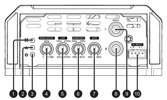
Gain adjustment procedure
To set the gain correctly, you will need a digital AC voltmeter and a 60Hz sine wave test tone recorded at 0dB.
- Turn gain control to minimum.
- Disconnect output cables from the amplifier.
- Set source unit volume to 3/4 of full volume.
- Set 'LOW' crossover to 20kHz and 'SUBSONIC' to 10Hz.
- Play the 60Hz sine wave.
- Increase gain until the 'CLIP' LED starts blinking.
- Return gain slightly until the 'CLIP' LED stops blinking and remains off.
- Turn off the source unit and reconnect speakers.
Bass boost and crossovers
The amplifier features a semi-parametric bass boost (0 to +12dB at 50Hz). The crossovers allow for bandpass filtering: use the 'SUBSONIC' control (10Hz - 80Hz) for the high-pass cut and the 'LOW' control (50Hz - 20kHz) for the low-pass cut.
Technical specifications
- Power RMS @ 4Ω: 535W (2Ω model) / 800W (4Ω model)
- Power RMS @ 2Ω: 800W (2Ω model)
- Operating Voltage: 8V - 16V
- Fuse: 40A
- Power Cable: 10mm² (7 AWG)
- Speaker Cable: 2 x 2mm² (12 AWG)
Practical help
Common problems
Amplifier not turning on
Check the remote connection or ensure the High Level input signal is present. Verify battery voltage is between 12.6V and 14.4V.
Ground loop noise
Ensure the amplifier is not mounted directly on metallic parts of the vehicle and the ground cable is as short as possible.
Amplifier overheating
Ensure the side ventilation windows are not blocked and clean the heatsink periodically with a brush or dry cloth.
Before use
- Disconnect the negative battery terminal.
- Check battery voltage (12.6V - 14.4V).
- Use 10mm² (7 AWG) power cables.
- Install a 40A fuse within 12 inches of the battery.
- Verify all connections before powering on.
- Ensure proper ventilation for the heatsink.
Specs in practice
- Operating Voltage
- 8V - 16V range; optimal performance at 12.6V - 14.4V.
Images and diagrams
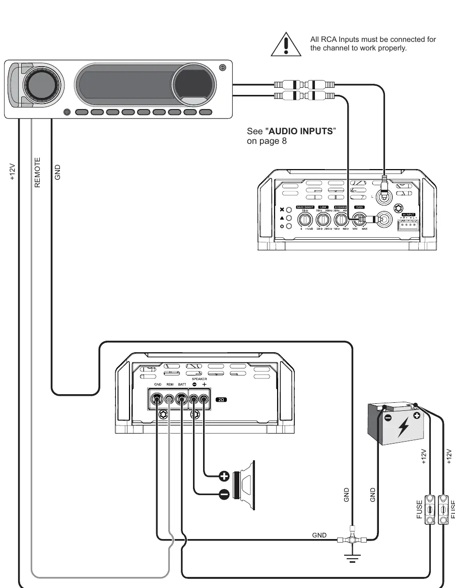
- The wiring diagram shows the connection of +12V, Remote, and Ground, along with RCA/High Level inputs and speaker outputs.
- The panel description identifies the LED indicators (Protection, Clip, Power On) and control knobs for Bass Boost, Low Pass, Subsonic, and Gain.
Model compatibility
- Do not use RCA and High Level inputs simultaneously.
- Use only OFC (Oxygen Free Copper) cables; do not use CCA cables.
- If the signal source is mono, use a 'Y' cable at the input.

Manual page author
David Miller
Documentation analyst
Organizes user manual content into clear summaries, with attention to model details, product context, and everyday usability.