Power / Batteries & Chargers
User Manual for Stanley HG80 Hydraulic Grinder
Quick guide for the Stanley HG80 Hydraulic Grinder. Includes safety precautions, hose connection instructions, grinding wheel installation, troubleshooting, and technical specifications.
Table of contents
Manual images
Click an image to enlargeQuick guide from the manual
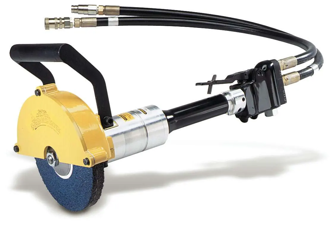
The Stanley HG80 is a hydraulic grinder designed for professional use. Before operation, ensure the hydraulic power source provides a flow of 7–10 GPM (26–38 LPM) at 1500–2000 PSI (105–140 bar). Always wear appropriate personal protective equipment, including goggles, ear and head protection, and safety shoes. Ensure the grinding wheel is correctly mounted and tightened before use. Always connect hoses to the tool before energizing the hydraulic power source.
Safety Precautions
- Do not operate the tool with the wheel guard removed.
- Never wear loose clothing that can get entangled in the working parts.
- Keep all body parts away from the rotating wheel.
- Do not use a wheel that is cracked, chipped, or damaged.
- Do not reverse grinding wheel rotation by changing fluid flow direction.
- Do not operate the tool at oil temperatures above 140°F (60°C).
- Use only abrasive wheels that comply with ANSI B7.1/ISO 525, 603.
- If the material creates dust or fumes, use personal protective devices.
Hose Requirements and Connections
The hydraulic hose must have a rated working pressure equal to or higher than the relief valve setting on the hydraulic system. There are three types of hoses: Certified non-conductive, Wire-braided (conductive), and Fabric-braided. Only certified non-conductive hose is authorized for use near electrical conductors.
Connection Procedure:
- Wipe all hose couplers with a clean lint-free cloth before connecting.
- Connect the return hose first and disconnect it last to minimize trapped pressure.
- Observe flow indicators on couplers to ensure correct oil flow direction. The female coupler is the inlet.
- Ensure the hydraulic circuit matches the tool for open-center or closed-center operation.
Operation
Installing and Removing Grinding Wheels:
- Loosen the 3 capscrews and remove the guard front plate.
- Depress the push lock to lock the spindle.
- Unscrew the jam nut and remove the outside flange.
- Install the grinding wheel onto the spindle and reinstall the flange and jam nut.
- Tighten the jam nut only sufficiently to prevent slippage.
- Reinstall the guard front plate and secure with capscrews.
Operating Procedures:
- Start the grinder with the wheel away from the work surface.
- Move the hydraulic circuit control valve to the ON position.
- Squeeze the trigger momentarily to verify operation.
- Grind a small amount of material at a time.
Maintenance and Care
- Always store the tool in a clean, dry space.
- Keep all warning stickers and tags legible.
- Tool repair and service must only be performed by authorized and trained personnel.
- If the grinder is dropped with a wheel installed, examine the wheel thoroughly before use.
Troubleshooting
- Grinder does not run: Check power source for proper flow and pressure, check for blocked hoses, or ensure lines are connected.
- Grinder operates too slow: Check for high back-pressure, blocked hoses, oil temperature issues, or incorrect relief valve settings.
- Grinder operates too fast: Flow control may be malfunctioning; have it serviced at an authorized Stanley service center.
Specifications
- Wheel Capacity: 8 in. dia. x 1 in. thk x 5/8 arbor (Type 1)
- Pressure Range: 1000–2000 PSI (70–140 bar)
- Flow Range: 7–10 GPM (26–38 LPM)
- Optimum Flow: 10 GPM (38 LPM)
- Max Back Pressure: 250 PSI (17 bar)
- Max Fluid Temperature: 140°F (60°C)
- Weight: 14.1 lb (6.40 kg)
Practical help
Common problems
Grinder does not run
Check hydraulic power source for proper flow and pressure (7–10 GPM @ 1500–2000 PSI). Inspect for blocked hoses or disconnected lines.
Grinder operates too slow
Check for high back-pressure (over 250 PSI), blocked hoses, or incorrect oil temperature. Ensure relief valve is set to 2100–2250 PSI.
Grinder operates too fast
Flow control may be malfunctioning. Have the unit serviced at an authorized Stanley service center.
Before use
- Inspect the tool for structural damage or leaks.
- Ensure the grinding wheel is correctly mounted and tightened.
- Verify hydraulic power source flow and pressure settings.
- Wipe all hose couplers clean before connection.
- Wear required PPE: goggles, ear/head protection, and safety shoes.
- Ensure the wheel guard is properly installed.
Specs in practice
- Pressure Range
- 1000–2000 PSI (70–140 bar) is the operating pressure range.
- Max Back Pressure
- 250 PSI (17 bar) is the maximum allowable pressure at the return hose end.
- Max Fluid Temperature
- 140°F (60°C) is the maximum operating temperature for hydraulic fluid.
Images and diagrams
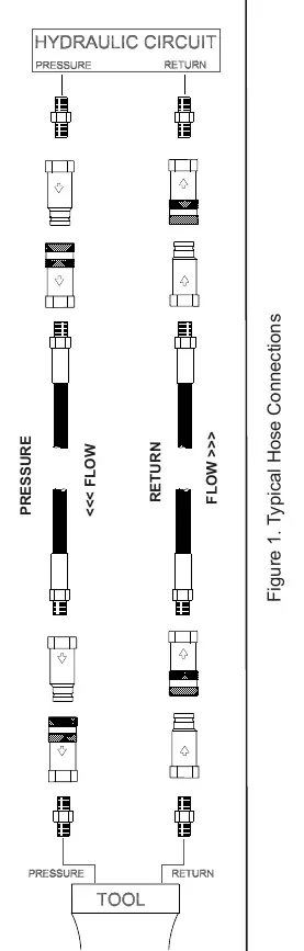
- Figure 1 illustrates the correct hose connection setup, showing the pressure hose connected to the 'IN' port and the return hose to the 'OUT' port.
Model compatibility
- Use 8-inch diameter by 1-inch thick (Type 1) grinding wheels with a 5/8 arbor hole.
- Grinding wheels must comply with ANSI B7.1/ISO 525, 603 standards.
- Only use certified non-conductive hose when working near electrical conductors.

Manual page author
Emily Carter
User documentation editor
Prepares concise manual descriptions and highlights the most useful setup, operation, and maintenance information for readers.