Industrial / Material Handling
User Manual for Stealth 13V2S12-CAD Electric Winch
Comprehensive user manual for the Stealth 13V2S12-CAD electric winch. Includes installation instructions, wiring diagrams, rigging techniques, maintenance procedures, troubleshooting, and safety guidelines.
Table of contents
Manual images
Click an image to enlargeQuick Guide from the Manual
This winch is designed for intermittent use only. Always allow the motor to cool down after heavy use. Do not exceed the rated capacity of 13,500 lbs. Ensure the vehicle engine is running during winching to prevent battery drain. Always use gloves when handling the wire rope and keep hands clear of the fairlead and drum during operation.
Important Safety Instructions
- Rated Capacity: Do not exceed the maximum pull rating.
- Intermittent Use: The winch is for intermittent use. If the motor becomes hot, stop and let it cool for approximately 8 minutes.
- Safety Distance: Keep people and animals at a safe distance from the cable when under tension.
- No Hoisting: Never use the winch for lifting people, live animals, or overhead hoisting.
- Cable Handling: Always keep at least 5 wraps of cable on the drum. Never let the cable slide through your hands.
- Modifications: Do not cut, weld, or modify any part of the winch or cable.
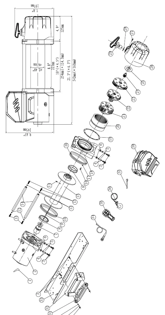
Winch Assembly and Mounting
The winch features a standard bolt pattern. Ensure it is mounted on a flat surface to allow proper alignment of the motor, drum, and gear housing. Poor installation can lead to equipment damage. Connect the roller fairlead to the mounting channel using the provided M10 bolts, washers, and nuts. Ensure the cable feeds from the bottom of the drum (under-wind).
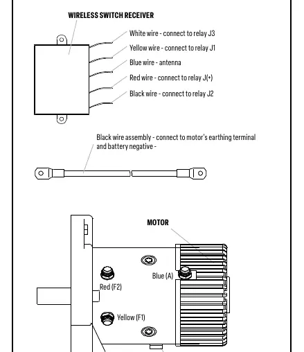
Wiring
Connect the battery and motor leads according to the wiring diagram provided in the manual. Ensure the black wire assembly is connected to the motor's earthing terminal and the battery negative. The red wire connects to the battery positive. Ensure all connections are tight and free of corrosion.
Rigging and Winching Techniques
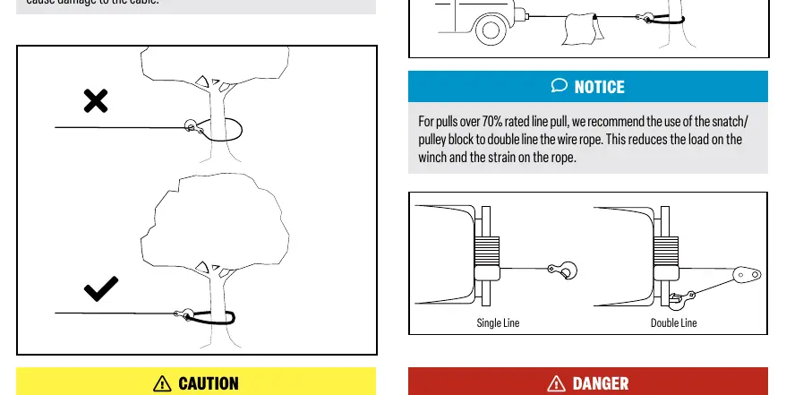
Always use a sling or strap as an anchor point; never attach the hook back onto the cable itself. For pulls over 70% of the rated line pull, use a pulley/snatch block to double the line, which reduces strain on the winch and rope. When pulling a heavy load, place a blanket or jacket over the wire rope to dampen the force in case of a cable break.
Maintenance
Periodically check the tightness of all mounting bolts and electrical connections. Keep the winch clean and free of dirt or corrosion. The gear box is sealed at the factory and requires no internal lubrication. If the wire rope shows signs of fraying, replace it immediately with an identical replacement part.
Troubleshooting
If the motor does not turn on, check remote lead connections, battery connections, or the remote assembly. If the motor runs but the drum does not turn, ensure the clutch is engaged. If the motor runs slowly, ensure the vehicle engine is running to provide sufficient current. For braking malfunctions, adjust the cable working direction or check the brake slice.
Practical help
Common problems
Motor does not turn on
Check remote lead and connections, check battery connections, or replace defective remote/motor.
Motor runs but drum does not turn
Ensure the clutch is engaged (turn to 'IN' position).
Motor runs slowly or lacks power
Operate the winch while the vehicle engine is running to ensure sufficient voltage.
Motor overheating
Winch is running for too long; allow it to cool down periodically.
Winch runs in one direction only
Clean and tighten battery/motor cable connections or repair/replace the switch assembly.
Before use
- Inspect wire rope for fraying or damage.
- Ensure all mounting bolts are tight.
- Check battery connections for tightness and corrosion.
- Ensure the clutch is engaged before operation.
- Wear gloves and eye protection.
- Ensure the vehicle is secured and in neutral (if applicable).
Specs in practice
- Rated line pull
- 13,500 lbs (6123 kgs) maximum capacity on the first layer.
- Gear reduction ratio
- 265:1, determining the torque and speed.
Images and diagrams
- Wiring diagram shows relay connections (J1, J2, J3, J+) and motor terminals (F1, F2, A).
- Assembly drawing illustrates the sequence of gear components, drum, and housing.
Model compatibility
- Designed for 12V or 24V battery systems.
- Use only manufacturer-supplied accessories and replacement parts.
- Not designed for overhead lifting or securing loads during transport.

Manual page author
Emily Carter
User documentation editor
Prepares concise manual descriptions and highlights the most useful setup, operation, and maintenance information for readers.