Industrial / Material Handling
User Manual for Vevor 0.5-H and 1T-H Manual Trolley
Get started with your Vevor 0.5-H and 1T-H manual trolley. This guide covers installation, safety inspections, load capacity, and maintenance procedures for safe operation.
Table of contents
Manual images
Click an image to enlargeQuick guide from the manual
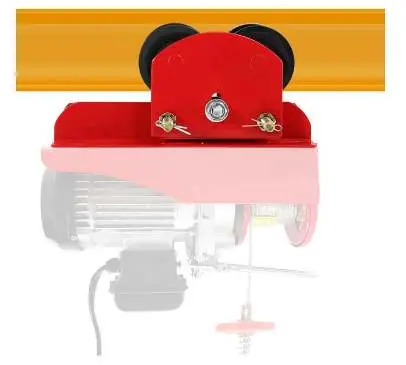
This manual provides instructions for the Vevor 0.5-H and 1T-H manual trolleys. These devices are designed for the horizontal transport of loads by hand when coupled with an electric hoist. Before operation, ensure the mounting structure has sufficient strength and that the trolley is compatible with your specific electric hoist model. Always perform a safety inspection before use and ensure all nuts are tightened securely.
Intended purpose
The manual trolley is designed for horizontally transporting loads by hand using an electric hoist under normal atmospheric conditions. Compatibility is as follows:
- 0.5-H Trolley: Suitable for PA200-PA500 electric hoists.
- 1T-H Trolley: Suitable for PA600-PA1000 electric hoists.
Installation
There are two primary methods for installing the trolley onto a beam:
- Standard Installation: The preferred method is to slide the trolley onto the beam from the end. Ensure the chain hoist and trolley are coupled.
- Alternative Installation: If there is no space at the end of the beam, remove the side plate from the suspension shaft. Place the side plate on the other side of the flange, then re-assemble and re-install the side plate. Securely bend the split pin of the shaft stopper pin.
Important Installation Steps:
- Fit travel limit stops (not provided) at the end of the runway.
- Adjust the trolley using spacer washers so the dimension between the trolley wheel flanges is approximately 1/4 inch (6mm) greater than the runway beam width.
- After installation, check that all nuts are correctly tightened.
- Suspend a light load to ensure all four wheels contact the runway beam.
- Once fitted, suspend the Maximum Safe Working Load and run the unit slowly along the full length of the beam to ensure satisfactory operation.
- Check that the clearance between the beam's outer edge and the trolley wheel is equal on both sides.
Safety inspection
Safety is critical when transporting heavy loads. Perform the following checks:
- Verify that the mounting structure has sufficient strength to hold the load.
- Ensure the trolley and the capacity of the lifting equipment are suitable for the job.
- Visually inspect the trolley for any damage or storage issues.
- Check the load bar for wear, defects, deformations, or corrosion marks before every use.
- Ensure the load bar is assembled correctly.
- Secure nuts with lockouts; they must be tight.
Maintenance
To maintain the trolley in good working condition:
- Avoid prolonged exposure to the sun to prevent aging of components.
- Regularly check for wear, defects, and corrosion.
- Ensure all nuts remain tightened and secure.
Technical specifications
The following specifications apply to the models:
- 0.5-H: Load Capacity 0.5 Ton (1100 lbs); Rail width 2.36-4.72 inches (60-120mm).
- 1T-H: Load Capacity 1 Ton (2200 lbs); Rail width 2.68-4.33 inches (68-110mm).
- Colour: Orange.
Main structure
The trolley consists of the following components:
- 1. Side Locking Nut
- 2. Trolley Pin
- 3. Side Plate
- 4. Steel Wheel
- 5. Casing Gaskets
- 6. Bracket
- 7. Mounting Hole
For technical support or warranty inquiries, please visit www.vevor.com/support.
Official resources from the manual
Manufacturer information
VEVOR
Practical help
Common problems
Trolley wheels not contacting the beam
Suspend a light load to the trolley to ensure all four wheels contact the runway beam, then screw the nuts tightly against the washers and secure with lockouts.
Insufficient clearance between wheel flanges and beam
Assemble the required number of spacer washers equally to the inside of the trolley side plates so the dimension is about 1/4 inch (6mm) greater than the beam width.
Signs of wear or corrosion
Check the load bar for wear, defects, deformations, or corrosion marks before every use. Do not use if damaged.
Before use
- Verify the mounting structure has sufficient strength.
- Check that the trolley is undamaged.
- Ensure the trolley capacity matches the electric hoist.
- Check that all nuts are correctly tightened.
- Verify the load bar is assembled correctly.
- Ensure travel limit stops are installed on the beam.
Specs in practice
- 0.5-H Load Capacity
- 0.5 Ton (1100 lbs)
- 1T-H Load Capacity
- 1 Ton (2200 lbs)
- 0.5-H Rail Width
- 2.36-4.72 inches (60-120mm)
- 1T-H Rail Width
- 2.68-4.33 inches (68-110mm)
Images and diagrams
- 1. Side Locking Nut
- 2. Trolley Pin
- 3. Side Plate
- 4. Steel Wheel
- 5. Casing Gaskets
Model compatibility
- 0.5-H model is suitable for PA200-PA500 electric hoists.
- 1T-H model is suitable for PA600-PA1000 electric hoists.

Manual page author
David Miller
Documentation analyst
Organizes user manual content into clear summaries, with attention to model details, product context, and everyday usability.