Industrial / Material Handling
User Manual for Vevor Monorail Trolley 0.5T-H and 1T-H
Quick guide for Vevor Monorail Trolley (0.5T-H, 1T-H). Includes installation steps, safety inspections, maintenance, and technical specifications for horizontal load transport.
Table of contents
Manual images
Click an image to enlargeQuick guide from the manual
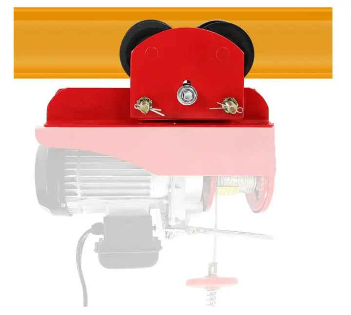
This document provides essential instructions for the Vevor Monorail Trolley, models 0.5T-H and 1T-H. These devices are designed for horizontal load transport using an electric hoist. Users must read the full manual before operation to ensure safety and proper installation. Key requirements include verifying load capacity, ensuring correct nut tightening, and confirming beam compatibility.
Safety Instructions
- Read the manual: Always read the instructions carefully before operating the equipment to reduce the risk of injury.
- Operating environment: Use only in well-ventilated areas. The device is intended for industrial use in ambient temperatures from 0°F to 130°F (-20°C to +50°C).
- Supervision: This appliance is not intended for use by persons (including children) with reduced physical, sensory, or mental capabilities unless supervised.
- Pre-use check: Always check the product for abnormalities before use. If any issues are found, stop using the equipment immediately.
Installation of trolley onto beam
There are two primary methods for installing the trolley:

- From the end of the beam: This is the preferred method. Couple the chain hoist and the trolley, slide them onto the beam, and ensure all nuts are correctly tightened. Install travel limit stops (not provided) at the end of the runway.
- Removing the side plate: If there is no space at the end of the beam, remove the side plate from the suspension shaft. Place the side plate on the other side of the flange, reassemble, and reinstall. Ensure the split pin of the shaft stopper pin is securely bent.
Safety Inspection
Regular inspections are critical for safe operation:
- Structural integrity: Ensure the mounting structure has sufficient strength to hold the load.
- Capacity check: Verify that the trolley and lifting equipment capacity are suitable for the job.
- Wheel contact: After initial installation, suspend a light load to ensure all four wheels contact the runway beam.
- Clearance: Once fitted, check that the clearance between the beam's outer edge and the trolley wheel is equal on both sides.
- Load bar: Check the load bar for wear, defects, deformations, or corrosion before every use.
Intended purpose
The trolley is designed for horizontally transporting loads by hand via an electric hoist. Compatibility is as follows:
- 1100lbs trolley (0.5T-H): Suitable for PA200-PA500 electric hoists.
- 2200lbs trolley (1T-H): Suitable for PA600-PA1000 electric hoists.
Main structure
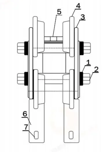
The trolley consists of the following components:
- Side Locking Nut
- Trolley Pin
- Side Plate
- Steel Wheel
- Casing Gaskets
- Bracket
- Mounting Hole
Maintenance
Proper maintenance ensures longevity and safety:
- Adjustment: When coupling the trolley to a hoist, use adjusting spacers. Assemble the required number of spacer washers equally to the inside of the side plates so that the dimension between the Trolley Wheel Flanges is about 1/4 inch (6mm) greater than the runway beam width.
- Storage: Avoid prolonged exposure to the sun to prevent aging of materials.
Manufacturer information
VEVOR
Practical help
Common problems
Trolley wheels do not fit the beam width
Adjust the number of spacer washers on the inside of the side plates to achieve a clearance of about 1/4 inch (6mm) greater than the beam width.
Unstable operation or uneven wheel contact
Suspend a light load to verify all four wheels contact the beam. Ensure all nuts are tightened securely against washers and lockouts.
Abnormal wear or damage
Stop using the equipment immediately. Inspect the load bar and structure for defects, deformations, or corrosion.
Before use
- Check the load bar for wear, defects, or corrosion.
- Verify the trolley capacity matches the hoist and load requirements.
- Ensure all nuts are correctly tightened.
- Confirm beam end stops are installed.
- Check that all four wheels contact the runway beam.
- Verify the trolley is free of abnormalities.
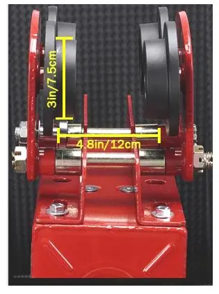
Specs in practice
- Adjust range
- 2.68-4.33 inches (the width of the beam the trolley can accommodate).
- 0.5T-H Capacity
- 1100 lbs (suitable for PA200-PA500 electric hoists).
- 1T-H Capacity
- 2200 lbs (suitable for PA600-PA1000 electric hoists).
Images and diagrams
- 1. Side Locking Nut
- 2. Trolley Pin
- 3. Side Plate
- 4. Steel Wheel
- 5. Casing Gaskets
Model compatibility
- Compatible with PA200-PA1000 series electric hoists depending on the trolley model.
- Designed for industrial use in ambient temperatures from 0°F to 130°F (-20°C to +50°C).

Manual page author
Emily Carter
User documentation editor
Prepares concise manual descriptions and highlights the most useful setup, operation, and maintenance information for readers.