Home / Smoke Detectors
Installation and Maintenance Instructions for System Sensor 2351BR Intelligent Photoelectric Smoke Sensor
A comprehensive guide for the System Sensor 2351BR and 2351BR-IV intelligent photoelectric smoke sensors. Includes detailed instructions on wiring, address setting, installation, testing procedures, and maintenance/cleaning steps.
Quick answers from the manual
Quick answer
- The 2351BR is an intelligent photoelectric smoke sensor. Installation requires wiring the base, setting the address via rotary switches, and mounting the sensor. It supports periodic testing via magnet, aerosol, or remote methods and requires cleaning of the sensing chamber if performance degrades. p. 1, 2
Key actions
- Install the sensor p. 1
- Clean the sensor p. 2
First start
- Set address and install p. 1
Show 4 more answers Show less
Problems and fixes
Sensor fails test
Clean the sensing chamber and screen, then retest.
p. 2Maintenance and reset
- Periodic cleaning p. 2
Technical specifications
| Parameter | Value | Meaning | Pages |
|---|---|---|---|
| Operating Voltage | 15 to 32 VDC | Required voltage range | p. 1 |
| Operating Temperature | 32°F to 122°F (0°C to 50°C) | Standard operating temperature | p. 1 |
| Air Velocity | 0 to 4000 ft./min. | Air speed limit | p. 1 |
Where to find it in the PDF
- Specifications and Installation p. 1
- Testing and Cleaning p. 2
Table of contents
Manual images
Click an image to enlargeQuick guide from the manual
The System Sensor 2351BR and 2351BR-IV are intelligent, plug-in photoelectric smoke sensors designed for use with compatible control panels. Key operational requirements include:
- Installation: Must be installed in compliance with the National Electrical Code (NEC) and local codes.
- Wiring: Ensure proper wire gauges are used and connections are not looped under terminals 1 or 2.
- Testing: Sensors must be tested after installation and periodically thereafter. Methods include magnet testing, aerosol smoke, or remote testing.
- Maintenance: Dust covers must be removed before operation. Periodic cleaning of the sensing chamber is required to ensure proper function.
General Description
These sensors combine a photoelectronic sensing chamber with addressable-analog communications. They transmit an analog representation of smoke density to a control panel. The devices are point-addressable up to 159 addresses and support Advanced Protocol and CLIP (Classic Loop Interface Protocol) modes.
Installation and Wiring
Before installing, ensure power is removed from the communication line. Follow these steps:
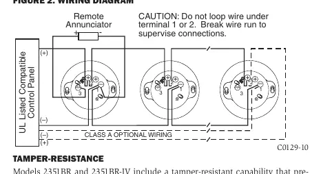
- Wire the sensor base (supplied separately) according to the wiring diagram.
- Set the desired address using the rotary address switches.
- Install the sensor into the base by pushing and turning clockwise until secure.
- Apply power to the control panel and activate the communication line.
Caution: Do not loop wire under terminal 1 or 2. Break the wire run to supervise connections.
Testing Procedures
Before testing, notify the proper authorities that the system is undergoing maintenance to prevent unwanted alarms.
- Functional Magnet Test: Hold the test magnet in the designated magnet test area. The sensor should alarm the panel.
- Smoke Entry Test: Use approved canned aerosol simulated smoke (e.g., HSI Fire & Safety 25S/30S, SDi Smoke Centurian/SoloA4/Smokesabre/Trutest, or No Climb Testifire 2000).
- Remote Test: Can be performed using RTS151 or RTS151KEY accessories.
Cleaning and Maintenance
If a sensor fails testing, it may require cleaning:
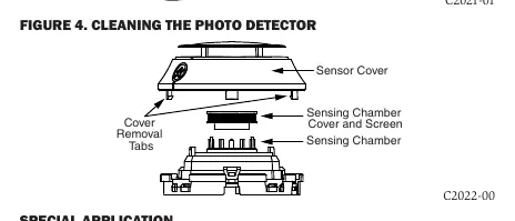
- Remove the sensor from the system.
- Press the four removal tabs to remove the sensor cover.
- Vacuum the screen carefully.
- If further cleaning is needed, pull the chamber cover/screen assembly straight out.
- Use a vacuum or compressed air to remove dust and debris from the sensing chamber.
- Reinstall the assembly, replace the cover, and retest the detector.
Special Application Mode
The detector can be configured for a special application mode with higher sensitivity. This mode is not for general use and is prone to false alarms in environments with airborne particulates (e.g., sawing, grinding, agricultural processing). Do not use this mode in areas where cooking appliances are present.
Technical Specifications
- Operating Voltage: 15 to 32 VDC
- Operating Current @ 24 VDC: 200 uA
- Maximum Alarm Current: 2 mA @ 24 VDC
- Operating Temperature: 32°F to 122°F (0°C to 50°C)
- Air Velocity: 0 to 4000 ft./min.
- Weight: 5.2 oz. (147 g)
Practical help
Common problems
Sensor fails functional or smoke test
Clean the sensing chamber and screen as described in the cleaning section, then retest.
False alarms in special application mode
Ensure the environment is free of airborne particulates like dust, sawing, or grinding debris. Switch to normal application mode if necessary.
Wiring faults or supervision errors
Ensure wires are not looped under terminal 1 or 2. Break the wire run at the terminals to allow for proper supervision.
Before use
- Remove dust covers before operation.
- Verify compatibility with the control panel.
- Ensure power is removed from the communication line before installation.
- Set the address using the rotary switches.
- Notify authorities before performing maintenance or testing.
Show more Show less
Specs in practice
- Operating Voltage
- 15 to 32 VDC range required for proper operation.
- Air Velocity
- The sensor is rated for air speeds between 0 and 4000 ft./min.
- Operating Temperature
- Standard operating range is 32°F to 122°F (0°C to 50°C).
Images and diagrams
- Figure 1: Shows the rotary address switches used to set the device address.
- Figure 2: Wiring diagram illustrating connections for the control panel and remote annunciator.
- Figure 4: Exploded view of the sensor showing how to remove the cover and chamber for cleaning.
Model compatibility
- Requires compatible addressable control panels.
- Supports Advanced Protocol and CLIP (Classic Loop Interface Protocol).
- Only use System Sensor approved accessories.

Manual page author
Emily Carter
User documentation editor