Automotive / Car Audio
User Manual for Taramps MD 12000.1 Car Amplifier
Quick guide for the Taramps MD 12000.1 car amplifier. Includes installation instructions, wiring diagrams, protection system explanations, and technical specifications.
Table of contents
Manual images
Click an image to enlargeQuick guide from the manual
The Taramps MD 12000.1 is a high-power car audio amplifier. This manual provides essential information for safe installation and operation. Key requirements include professional installation, the use of 12V batteries, and the installation of a 600A fuse or circuit breaker as close to the battery as possible. Ensure at least 1 inch (25mm) of space around the heatsink for proper ventilation.
Safety requirements
- Installation must be performed by a qualified professional.
- Always use 12V batteries.
- Use 70mm² (2/0 AWG) cables for power supply.
- Install a 600A fuse or circuit breaker near the battery.
- Keep the amplifier away from fuel tanks, fuel lines, and heat sources.
- Avoid touching the heatsink during operation as it becomes hot.
- Ensure the amplifier is turned off before making any connections.
Functions, inputs & outputs
The amplifier features several controls for sound adjustment:
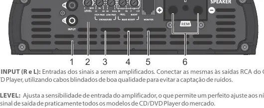
- Input (R and L): Connect to RCA outputs of your head unit using shielded cables.
- Level: Adjusts input sensitivity to match the head unit output.
- Crossover: Includes High Pass (10Hz-90Hz) and Low Pass (90Hz-5KHz) filters.
- Bass Boost: Adjusts frequency (35Hz-55Hz) and boost (0 to +10dB).
- Monitor: Connection for an optional accessory to monitor the amplifier.
- Speaker: Output terminals for transducer connection. Observe polarity and minimum impedance.
Power supply and installation
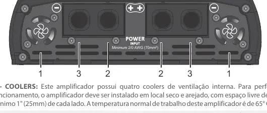
For optimal performance, use 70mm² (2/0 AWG) cables for both positive and negative power terminals. The negative cable should be as short as possible and connected to the battery negative pole. The amplifier includes four internal cooling fans; ensure these are not obstructed. The heatsink surface is designed to dissipate heat; do not cover it.

LED indicators and protection systems
The amplifier uses LEDs to indicate status:
- Blue LED steady on: Amplifier is turned on.
- Flashing yellow LED: Excessive temperature (approx. 80°C). The amplifier will reduce output to cool down. Do not turn off the amplifier; let the fans cool it.
- Blinking yellow LED (with music): Indicates operation at the threshold of distortion.
- Red LED steady on: Short-circuit or impedance lower than supported at the output.
- Red LED flashes 2x: Supply voltage less than 9V.
- Red LED flashes 3x: Supply voltage greater than 16V.
Technical features
The MD 12000.1 operates with a minimum output impedance of 0.5 Ohm or 1 Ohm depending on the version. It features a frequency response of 10Hz to 5KHz and an input sensitivity of 220mV. The unit requires a 9V to 16V DC power supply.
Practical help
Common problems
Red LED steady on
Indicates a short-circuit or impedance lower than supported at the output.
Red LED flashes 2x
Supply voltage is too low (less than 9V). Check battery and power connections.
Red LED flashes 3x
Supply voltage is too high (greater than 16V). Check charging system.
Yellow LED flashing
Excessive temperature (approx. 80°C). Ensure fans are not obstructed and ventilation is adequate. Do not turn off the amplifier.
Before use
- Ensure installation is performed by a qualified professional.
- Use 12V batteries.
- Install a 600A fuse or circuit breaker as close to the battery as possible.
- Use 70mm² (2/0 AWG) cables for power supply.
- Ensure at least 1 inch (25mm) of space around the heatsink.
- Verify that the negative cable is as short as possible.
Specs in practice
- Minimum Output Impedance
- 0.5 Ohm or 1 Ohm (depending on specific model version).
- Frequency Response
- 10Hz to 5KHz (-3dB).
- Input Sensitivity
- 220mV.
Images and diagrams
- The wiring diagram illustrates the connection of the 12V battery bank to the amplifier power terminals using 70mm² cables and a 600A fuse.
- The speaker connection diagram shows how to wire multiple speakers to achieve the required impedance (0.5 Ohm or 1 Ohm).
Model compatibility
- Requires 12V DC power source.
- Not suitable for use in places where children may be present.

Manual page author
Emily Carter
User documentation editor
Prepares concise manual descriptions and highlights the most useful setup, operation, and maintenance information for readers.