Electronics / Speakers & Soundbars
User Manual for Taramps MD 5000.1 Car Amplifier
Quick guide for the Taramps MD 5000.1 car amplifier. Includes installation instructions, wiring diagrams, LED indicator meanings, and technical specifications.
Table of contents
Manual images
Click an image to enlargeQuick guide from the manual
The Taramps MD 5000.1 is a high-performance car amplifier. Installation must be performed by a qualified professional. Ensure the vehicle's electrical system is 12V and that you use the recommended wire gauges and a 250A fuse or circuit breaker located as close to the battery as possible. Always disconnect the negative battery terminal before making any connections.
Functions, inputs and outputs
The amplifier features several controls to optimize audio performance:
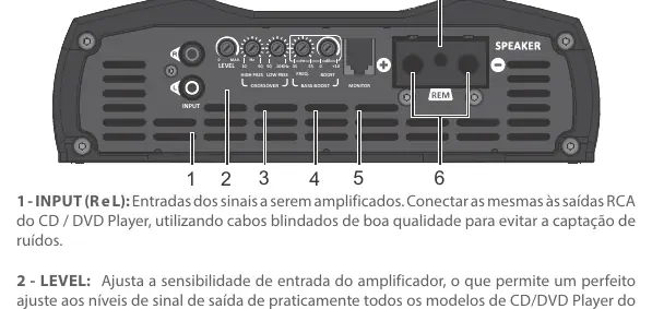
- Input (R and L): RCA inputs for connecting to your head unit. Use high-quality shielded cables.
- Level: Adjusts the input sensitivity to match your head unit's output.
- Crossover: Includes High Pass (HPF) variable from 10Hz to 90Hz and Low Pass (LPF) variable from 90Hz to 10KHz.
- Bass Boost: Adjustable frequency from 35Hz to 55Hz with a gain of 0 to +10dB.
- Monitor: Connection for an optional accessory to monitor amplifier status (not included).
- Speaker: Output terminals for connecting transducers. Ensure correct polarity and impedance matching.
- Remote Terminal: Connects to the remote output of the head unit using a 0.75mm² cable.
Power supply connection
Proper power connection is critical for performance and safety:
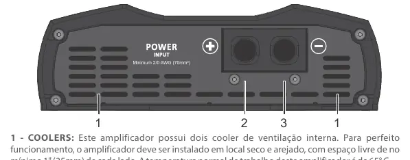
- Coolers: The amplifier has internal fans. Install in a cool, aired place with at least 1 inch (25mm) of space around the heatsink. Do not obstruct ventilation.
- Positive Terminal: Use a 70mm² (2/0 AWG) cable connected directly to the positive battery terminal with a 250A fuse.
- Negative Terminal: Use a 70mm² (2/0 AWG) cable connected to the negative battery terminal.
LED indicators and protection systems
The amplifier uses LED indicators to communicate status:
- Blue LED steady: Amplifier is on.
- Flashing yellow LED: Excessive temperature or distortion. The amplifier will reduce audio output until it cools down. Do not turn off the amplifier; let the fans run to cool it faster.
- Red LED steady: Short-circuit or low impedance detected at the output.
- Red LED flashes 2x: Supply voltage is below 9V.
- Red LED flashes 3x: Supply voltage is above 16V.
Installation and wiring
Follow these guidelines for a safe installation:
- Use 70mm² (2/0 AWG) cables for power and ground.
- Use 10mm² (7 AWG) cables for speaker outputs.
- Use a 0.75mm² (18 AWG) cable for the remote connection.
- Install a 250A protection fuse or circuit breaker.
- Ensure all cable ends are tinned for better electrical contact.
- The heatsink surface can get hot during operation; avoid contact.
Technical specifications
Key technical parameters include:
- Number of Channels: 1
- Frequency Response: 10Hz to 10KHz (-3dB)
- Input Sensitivity: 220mV
- Signal-to-Noise Ratio: >90dB
- Input Impedance: 15K Ohms
- Dimensions: 228 x 70 x 327mm
- Weight: 4.22Kg
Practical help
Common problems
Yellow LED flashing
Indicates excessive temperature or distortion. Keep the amplifier on to allow internal fans to cool the unit.
Red LED steady
Indicates a short-circuit or impedance lower than supported at the output.
Red LED flashes 2x
Supply voltage is too low (below 9V). Check battery and power connections.
Red LED flashes 3x
Supply voltage is too high (above 16V). Check charging system.
Before use
- Ensure installation is performed by a qualified professional.
- Use a 12V battery system.
- Install a 250A fuse or circuit breaker near the battery.
- Use 70mm² (2/0 AWG) cables for power supply.
- Ensure at least 1 inch (25mm) of space around the heatsink for ventilation.
- Disconnect the negative battery terminal before starting installation.
Specs in practice
- Minimum Output Impedance
- 1 Ohm or 2 Ohms depending on the specific model configuration.
- Frequency Response
- The range of frequencies the amplifier can reproduce (10Hz - 10KHz).
- Input Sensitivity
- 220mV, allows adjustment to match various head unit output levels.
Images and diagrams
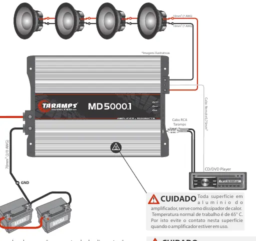
- Wiring diagram shows connection from battery to amplifier using 70mm² cables and a 250A fuse.
- Speaker connection diagram illustrates impedance matching for 1 Ohm and 2 Ohm configurations.
Model compatibility
- Requires 12V vehicle electrical system.
- Not suitable for use in places where children may be present.

Manual page author
Michael Turner
Technical manual editor
Reviews PDF manuals for structure, safety notes, and practical product details so readers can find the right information quickly.